V800 Series High Performance Closed-Loop Vector Inverter User manual
10.3 APPLICATION IN MECHANICAL FACTORY
Use requirements: After 50 times' external sensor signal receiving, operate the frequency inverter with first
step from 20Hz to 20s forwardly and second step from 30Hz to 40s reversely. Then make a stop and wait for
the next operation.
10.3.1 CONFIGURATION
1. F0.3.33= 1 Controlling order to be the external terminal controlling
2. F0.3.35= 0002 Function model of external controlling terminal to be the three wire model 1
3. F1.0.03= 5 Time for accelerating: 5s
4. F1.0.04= 5 Time for slowing down: 5s
5. F3.0.00= 44 DI1 terminal id defined as timer 1's clock terminal
6. F5.2.20= 0100 Select timer 1 work model
7. F5.2.22= 50 Set number counting as 50
8. F6.0.00= 20 Set first velocity as 20Hz
9. F6.0.01= 30 Set second velocity as 30Hz
10. F6.1.15= 0011 Operation model selects the stop model of multi-velocity single cycle
11. F6.1.17= 0010 Set operating direction in second velocity as the reverse
12. F6.1.31= 20 Time running for first velocity: 20s
13. F6.1.32= 40 Time running for second velocity: 40s
14. FF.0.01= 40 Virtual output of SDO1 signal — timer 1's cycle arrives
15. FF.0.09= 7 Virtual input of SDl1 signal — positive shift FWD terminal
16. FF.0.02= 46 Virtual output of SDO2 signal — timer 2's cycle arrives.
17. FF.0.10= 19 Virtual input of SDl2 signal — three-line operating control
18. FF.0.17= 0010 Phase-reversing connection between SDO2 and SDl2
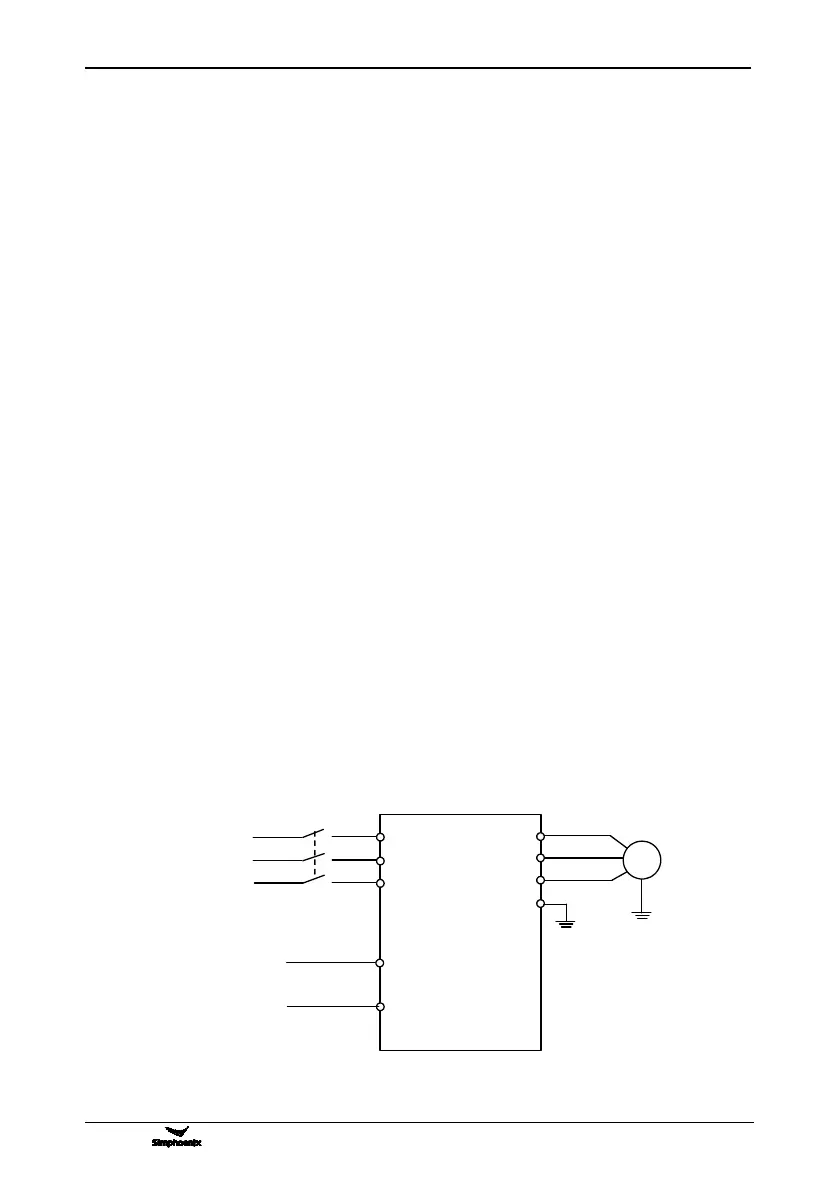
10.3.2 EXTERNAL CIRCUIT WIRING DIAGRAM
Three-phase
circuit breaker