Wiring Of Frequency Inverter
V800 Series High Performance Closed-Loop Vector Inverter User Manual
4.3 WIRING OF CONTROL TERMINAL
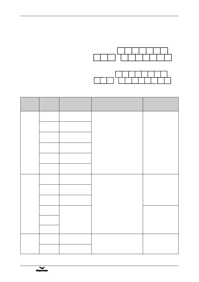
4.3.1 WIRING OF CONTROL PANEL STANDARD TERMINAL CON1、CON2、
CON3、CON4
4.3.2 FUNCTION DESCRIPTION OF CONTROL TERMINAL
Function description of terminal
Multifunctional input
terminal DI1
6 ways of programmable switching
value input terminal can be
selected 99 kinds of operational
control commands by function
code in F3.0 group by
programming.
See Reference Table for Input
Function Selection of
Multifunctional Terminal for detail.
Optical coupler
isolated input : 24Vdc
/5mA
Doorsill voltage : <16V
Bandwidth<1MHZ
Multifunctional input
terminal DI2
Multifunctional input
terminal DI3
Multifunctional input
terminal DI4
Multifunctional input
terminal DI5
Multifunctional input
terminal DI6
Common terminal of
input/output terminal
2 ways of programmable open
collector output and 1 way of
programmable relay output
terminal can be selected 71
kinds of operating status output
by the function code in F3.1
group by programming. See
Reference Table for Monitor
Unit Variables for detail.
Maximum load current
is 150mA; The highest
withstand voltage is
24V.
Multifunctional
output terminal DO1
Multifunctional
output terminal DO2
Multifunctional relay
output TA-TB
normally closed
TA-TC normally
open
Contact capacity:
AC250V/2A
+24V power supply
reference place
Power supply of switching value
terminal
Maximum output
current:100mA
Type I: CON3 and CON4 terminals
suitable model: inverter model below
V800-4T0030G/4T0040P
Type II: CON1 and CON2 terminals
suitable model: inverter model above
V800-4T0040G/4T0055P
DI1 DI3 DI5 DO1 24V
AI1
AO1 VS
DI2 DI4 DO2 CM AI2 AO2 GNDTA TB TC DI6
CON2
CON1