Installation Of Frequency Inverter
V800 Series High Performance Closed-Loop Vector Inverter User Manual
C
aptive screw
4T0450G/4T0550P
62.5KVA 95A/72.7KVA 115A
3.3 DISASSEMBLY AND INSTALLATION OF TERMINAL COVER
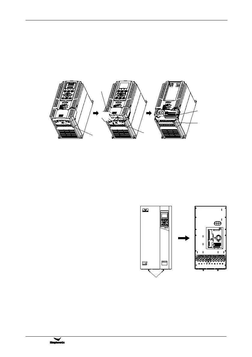
3.3.1 DISASSEMBLY AND INSTALLATION OF PLASTIC COVER PLATE
Put finger on the handle slot at the bottom of cover plate (the position of clasp as Figure 3-4), and forcibly lift
it upward until the card clasps between cover plate and shell break away, then pull the cover plate down can
disassemble the shell. Shown as Figure 3-4.
Slant cover plate into about 15°, then insert the fixed stator at the top of cover plate into fixed slot on shell.
Forcibly press the cover plate down until heard a click, which means the cover plate has been in place.
3.3.2 DISASSEMBLY AND INSTALLATION OF SHEET-METAL COVER PLATE
Disassembly and installation of sheet-metal cover plate are as shown in Figure 3-5.
1. Undo the two thumb screws at the bottom of cover
2. Translate the cover plate outward along direction of
icon then can dismantle it.
1. Place the cover plate down parallel to the chassis,
to make cover plate just seize up the both sides of
2. Push cover plate forward along direction of icon, to
make the stator at the top of cover plate insert into
3. Tighten up the two thumb screws at the bottom of
Figure 3-5 Schematic diagram of disassembly
and installation of sheet-metal cover plate
Figure 3-4 Disassembly and installation schematic diagram of plastic terminal cover
Lower cover plate
Front plugboard
Major loop
terminal
Control loop
terminal
Position of
handle clasp