Description Of Specific Functions
V800 Series High Performance Closed-Loop Vector Inverter User Manual
F0.4.51 Forward and reverse switch mode
0: Switch at zero point
To switch between FWD and REV at the zero point.
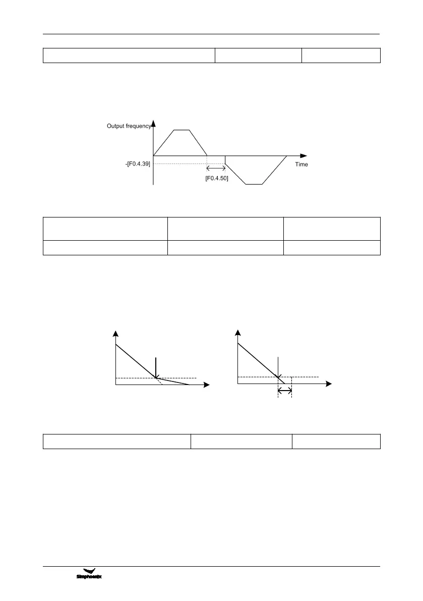
1: Start frequency switch
To switch between the FWD and REV at the start frequency. See the following figure:
F0.4.52 Zero speed
(frequency) detection level
Setting range: 0.00~100.00Hz
F0.4.53 Zero speed delay time
Setting range: 0.00~10.00Sec.
When the inverter output frequency is lowered to zero, it will immediately lock the output. At this time, the
motor revolution may not at zero, but the motor is completely at the free stop status, and will slide to stop.
Within the delay time, when the inverter output frequency is lower than the zero speed (frequency) detected
level [F0.4.52], within the zero speed delay time [F0.4.53], the inverter will keep working and output a DC
current, and the motor will keep excitation. The inverter may rapidly restart at any time.
F0.4.54 Emergency stop mode (EMS)
This parameter defines the stop mode after the inverter has received an emergency command (Function No.
14, to be set by the Group F3.0 parameters).
Figure 7-22 Sketch of start frequency FWD and REV switching
Figure 7-23 Comparison diagram when with or without zero speed delay
Time
[F0.4.53]
Speed
[F0.4.52]
Time
Speed
[F0.4.52]
No zero speed delay Zero speed delay