Description Of Specific Functions
V800 Series High Performance Closed-Loop Vector Inverter User Manual
F1.0.03~F1.0.08
Acceleration/ deceleration
time 1/2/3
Setting range: 0.01~600.00
F1.0.09 Acceleration 4/jog
acceleration time
Setting range: 0.01~600.00
F1.0.10 Deceleration 4/jog
deceleration time
Setting range: 0.01~600.00
The acceleration time means the time required for the inverter to accelerate from 0.00Hz to maximum output
frequency [F0.1.20].
The deceleration time means the time required for the inverter to decelerate from the maximum output
frequency [F0.1.20] to 0.00Hz.
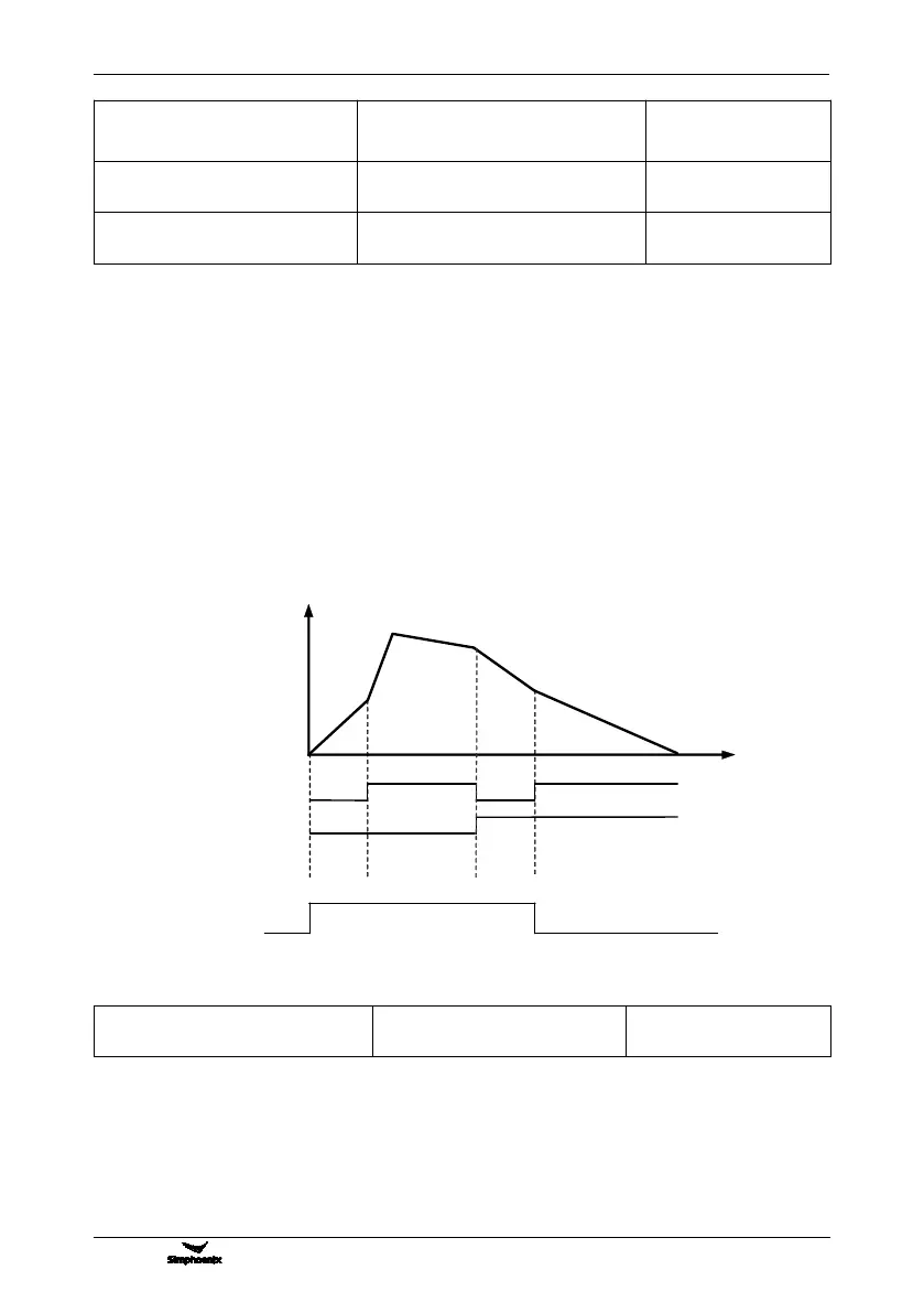
V800 series inverters are defined with 4 kinds of acceleration/deceleration time. The acceleration/
deceleration time 1~4 during the running process of the inverter can be selected through different
combinations of external terminals. During simple PLC running, it is also applicable to use them as the
acceleration and deceleration time at the time of switching among different running frequency at each stage.
See instructions of F6.1 group parameters for detail.
The acceleration/deceleration time 4/jog acceleration/deceleration time are also used as the acceleration
and declaration running time at the status of jog running. The jog frequency has the highest priority. At any
state, the inverter will immediately transit to the jog frequency running state according to the preset jog
acceleration and deceleration time as long as the jog command is inputted. (See the instructions of the
functional parameter F0.1.23 and F0.1.24) The unit (Sec., Min.) of the acceleration and deceleration time is
determined by the tens’ digit of the parameter F1.0.11.
F1.0.11 EMS emergency stop
and deceleration time
Setting range: 0.01~600.00
The time for decelerating from the maximum output frequency [F0.1.20] to the zero frequency will only
function when the inverter stops in deceleration way(F0.4.54 is set to 0) after receiving EMS emergency stop
command (Function No. 14).
Acceleration/deceleration
time selection terminal 1
Acceleration/deceleration
time selection terminal 2
Acceleration/
deceleration
Acceleration/
deceleration
Acceleration/
deceleration
Acceleration/deceleration
Figure 7-25 External terminal selection mode for acceleration and deceleration time
 Loading...