Tsunami Mode-Locked Ti-sapphire Laser
6-22
Aligning the Photodiode PC Board
Prior to aligning the photodiode pc board, the laser cavity must be properly
aligned (up to the AOM (fs) or bi-fi (ps) alignment). If necessary, align the
cavity according to the “Front-End Alignment” and either the “Cavity
Alignment for FS Systems” or “Cavity Alignment for PS Systems” section
earlier in this chapter.
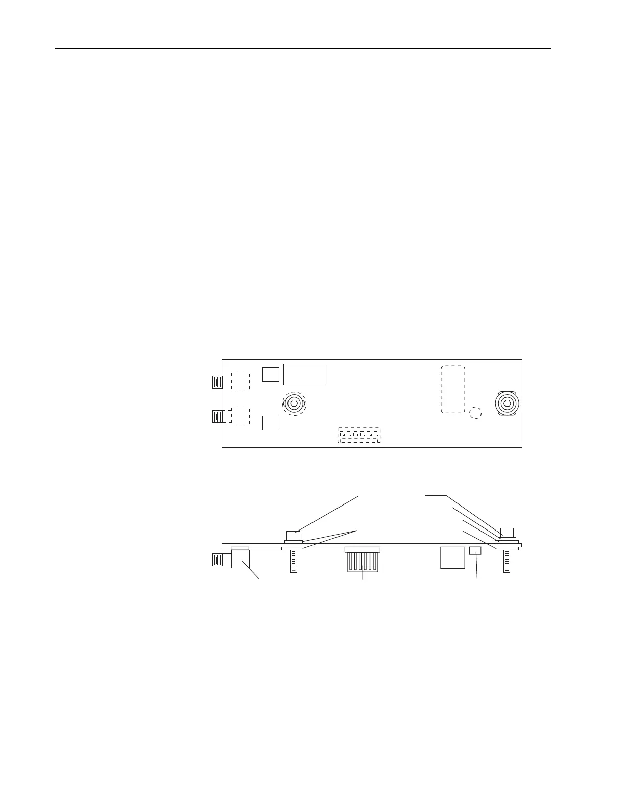
Figure 6-16 shows the layout of the Tsunami photodiode pc board. It is
located directly over the beam splitter as shown in Figure 6-13. The photo-
diode is a small, round can soldered to the bottom of the pc board. To align
the photodiode to the reference beam from the beam splitter, the pc board is
adjusted slightly to center the photodiode in the beam. Looking at the pc
board from the output bezel, note that the right mounting screw passes
through a narrow slot to allow lateral movement while a large rectangular
slot under the left mounting screw allows movement in all directions. The
photodiode is called out as CR
1
and is located just to the right of the left
mounting screw. To monitor the photodiode output signal level as you
move the board, observe the PHOTODIODE indicator on the front of the
Model 3955 electronics module.
Figure 6-16: Photodiode PC board
1. Refer to Table 6-4 and verify the correct photodiode board is installed
for the wavelength you are using. The assembly part number is located
in the lower left corner below the photodiode (Figure 6-16). If the cor-
rect board is installed, skip to Step 3.
61
3955
3930
J3
J1
CR1
J2
Cap Screw (2)
Small SS washer (1)
Small nylon washer (1)
Large nylon washer (3)
J
2
, J
3
Connectors J
1
Connector Photodiode
Top View
Side View
PHOTODIODE PCB
ASSY 0452-3280
ASSY 0452-3250 for > 900 nm