Tsunami Mode-Locked Ti-sapphire Laser
6-14
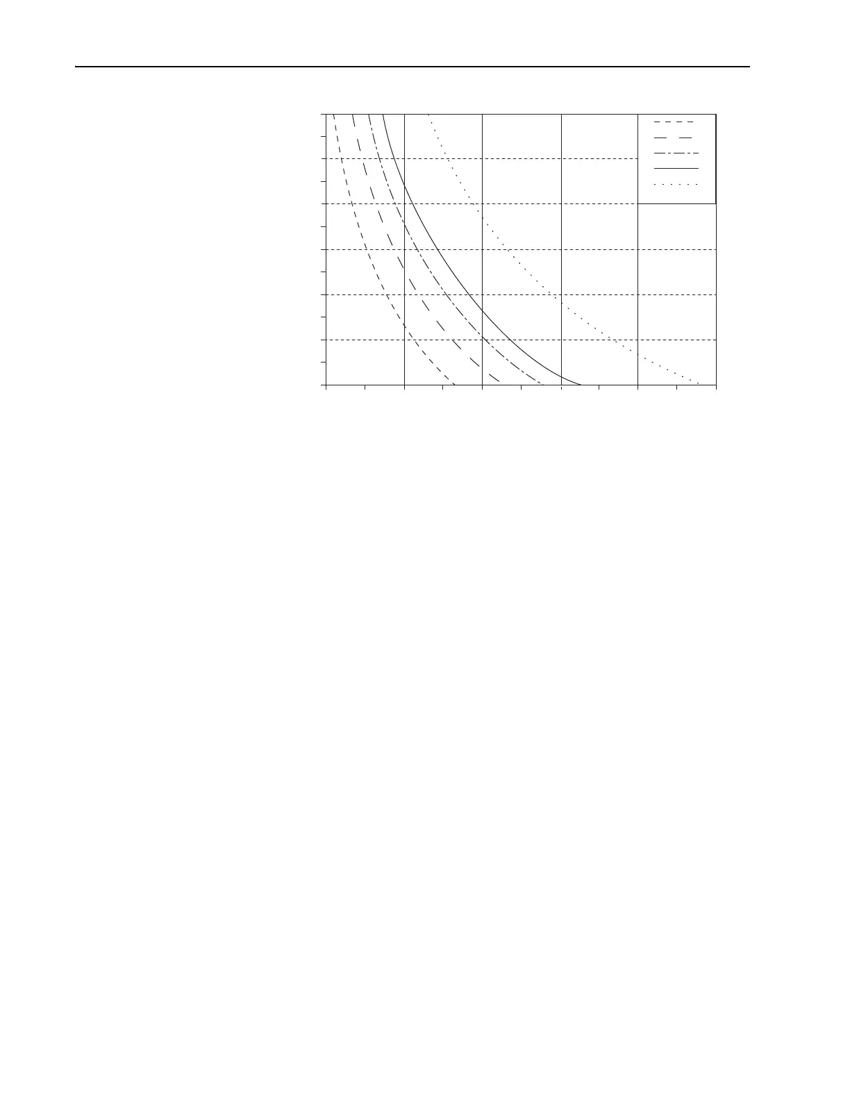
Figure 6-11: Bandwidth vs. Pulse Width for a Transform-limited sech
2
Pulse Shape.
3. Vary pump power and dispersion compensation to obtain the desired
output power and pulse width. (Bandwidth is subject to pump power
level as well as dispersion compensation in the cavity.)
4. Repeat Steps 1 through 3 until the Tsunami pulse is optimized and the
test in Step 4 of “Test for Proper Modelocking” later in this chapter is
successful.
This completes the AOM alignment and the fs cavity alignment.
Cavity Alignment for a PS System
1. Turn the pump laser up to the nominal power found in Step 6 of “Front
End Alignment” for the installed optic set. Refer to the tables in Chap-
ter 10 to correlate between the optics and the optic set.
2. Align fold mirrors
M
4
and M
5
.
a. Verify
M
4
and M
5
are in their correct positions for ps operation
(Figure 6-12).
b. Adjust M
3
to center the fluorescence on M
4
.
c. Adjust
M
4
to center the reflected images from M
3
and M
1
onto M
5
.
d. Place a white card in front of the input to the
A/O modulator
(
AOM).
e. Using an IR viewer, adjust
M
5
to guide the fluorescent spots
directly onto the card.
f. Remove the white card and place it about 10 cm outside the output
window.
710 nm
850 nm
790 nm
900 nm
1053 nm
40
50
60
70
80
90
100
51015202530
Bandwidth (nm)
Pulsewidth (fs)