Tsunami Mode-Locked Ti-sapphire Laser
6-20
e. Adjust the fine PHASE control slowly to find the position on the
PHASE LED bar graph where modelocking occurs.
f. Turn the PHASE knob to set the PHASE LED to the top bar. Repeat
the last four steps to find the other LED position for initiating
modelocking.
g. Adjust the fine PHASE control to center the LED position between
these two limits.
h. Repeat Steps a, band d above. If the phase adjustment is correct,
the system will return to modelocked status within a second.
After proper purging, the system should modelock over the entire tun-
ing range within a second or two if the fine PHASE control is tested as
described above. However, as cavity length changes as a function of
wavelength (except when the cavity frequency is locked to a constant
when the Lok-to-Clock option is used), the fine phase setting changes
as well. Provided that the cavity frequency throughout the entire tun-
ing range is within the frequency limit of the AOM, the fine
PHASE
LED
position goes upwards as the wavelength increases for non Lok-to-
Clock systems.
This completes the AOM alignment.
Selecting, Installing and Aligning the Birefringent Filter
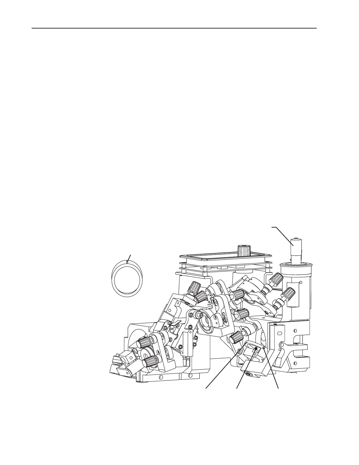
Figure 6-15: The Birefringent Filter
Setscrews
Bi-fi Wavelength Selector (ps)
12 o'clock
Position
Location
for Bi-fi
Filter Holder
Setscrew
Bi-fi