Alignment
6-17
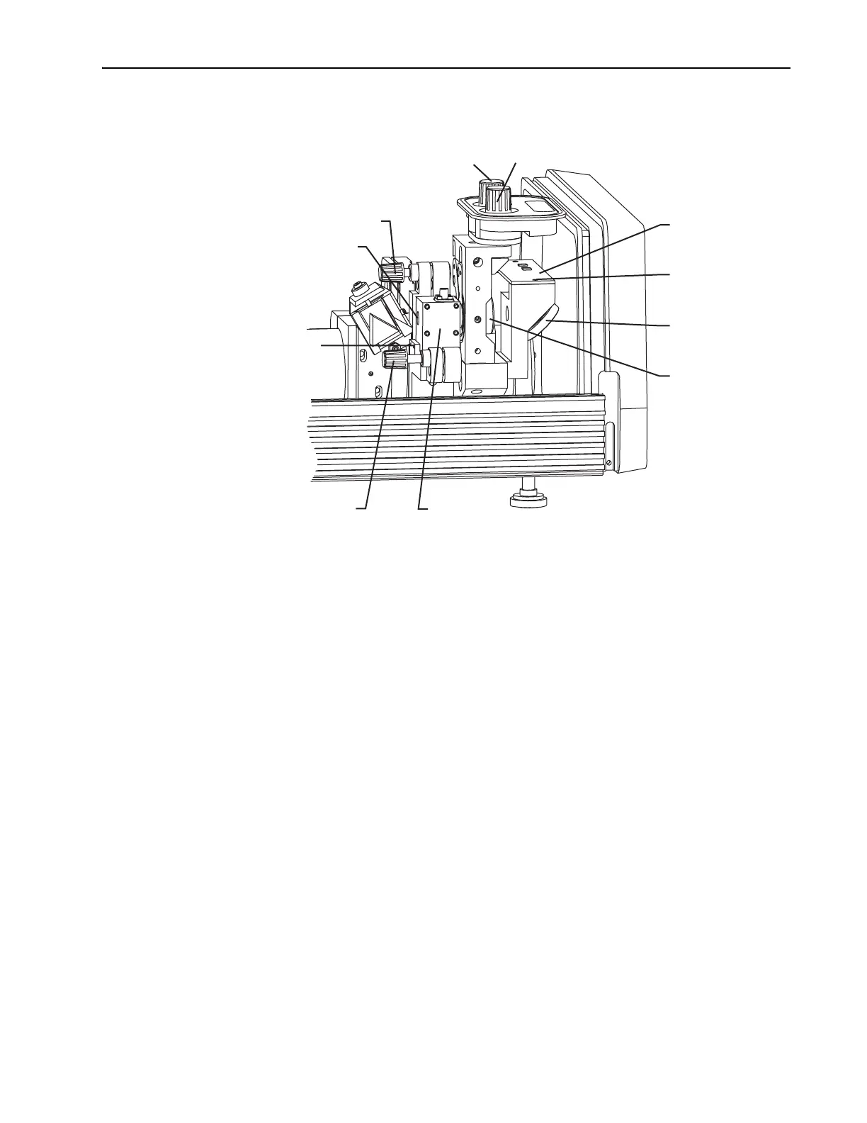
Figure 6-13: AOM, Output Coupler, Photodiode PC Board, and Beam Splitter
Place a white card between M
10
and the beam splitter, and use the edge
of the card to detect the position of the beam.
2. Use the vertical control knob of M
10
to detune the laser until it stops
lasing.
3. Verify the intracavity beam is centered in the AOM.
Use an IR viewer to see that the
M
3
/M
1
fluorescence is centered through
the silhouette of the AOM crystal. The fluorescence should not be near
the edges of the crystal. If necessary, loosen the
AOM mounting
bracket to adjust it vertically and horizontally. Two
2-56 setscrews hold
it horizontally while two
9
/64 in. cap screws keep it secured vertically.
4. Readjust M
10
vertically to reestablish lasing and to optimize output.
Establish Modelocking
1. Push the STATUS mode locker enable button (the ENABLE LED should
be on).
2. Set up an autocorrelator to aid in determining proper phase and GTI
POSITION dispersion compensation.
a. Increase the gain on the autocorrelator.
b. Adjust the crystal angle on the autocorrelator to obtain an oscillo-
scope signal trace (Figure 6-14, a–c).
Output Coupler (M
10
)
Positioning Controls
Horz. Vert.
Photodiode
PC Board
Mounting
Screws (2)
Beam
Splitter
Output
Coupler (M
10
)
AOM Pitch Control
AOM Aperture Window
AOM Mounting Setscrews (2)
AOM Horizontal
Angle Control
AOM