C-1
Appendix C Setting the Line Voltage Switch
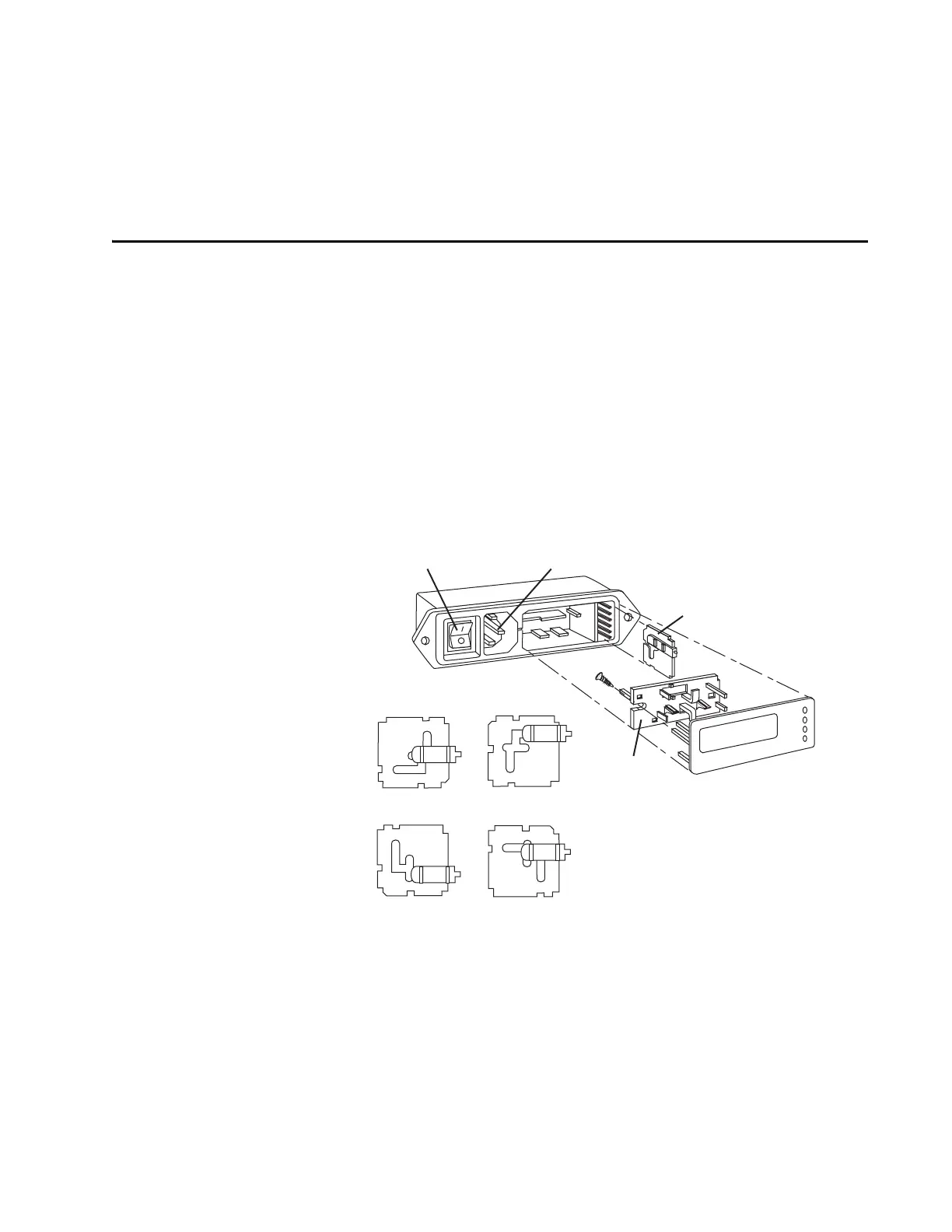
The line voltage switch, which is part of the power connector on the Model
3955 electronics module, must match your local line voltage. The Model
3955 and optional Model 3930 are shipped from the factory with the line
voltage selected for the location of intended use. If the incorrect setting is
selected, you must change it prior to applying power to the system. The fol-
lowing directions are provided so you can make the change yourself.
1. Remove the cover plate/fuse block assembly to expose the voltage sel-
ector card. Refer to Figure C-1
Use a small screwdriver to gently pry off the cover plate. A slot is pro-
vided for screwdriver access.
Figure C-1: Power Switch, Line Cord, and Voltage Selector Module
2. Remove the voltage select card.
The voltage select card comprises a white plastic indicator pin and a
small pc board about 2 cm square. Refer to Figure C-1.
Using needle-nose pliers, gently grasp the pc board and pull it out and
from side to side to remove it from the module.
4
0
220 V
2
2
0
2
2
0
1
1
0
0
4
0
2
2
0
2
2
0
1
1
0
0
110 V
4
0
2
2
0
2
2
0
1
1
0
0
4
0
2
2
0
2
2
0
1
1
0
0
120 V
240 V
Voltage Selector
Card
The four orientations of the voltage selector card.
Power Switch
Power Cord Connector
Fuse
Holder Bracket
120 V
220 V
2
40 V
100 V