Tsunami Mode-Locked Ti:sapphire Laser
4-10
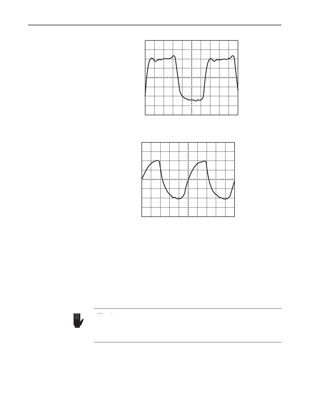
Figure 4-7: Typical MONITOR signal (DC offset: 0 V) as shown on a
1 GHz bandwidth oscilloscope.
Figure 4-8: Typical SYNC signal (DC offset: –1.25 V) as shown on a
1 GHz bandwidth oscilloscope.
SYNC BNC connector—connects to a 1 MΩ oscilloscope trigger input for
viewing the MONITOR photodiode signal. A typical waveform is shown in
Figure 4-8. This signal can also drive other Spectra-Physics products, such
as the Model 3985 pulse selector. This is a negative signal. The signal
amplitude shown is approximate and depends on operating wavelength,
power and photodiode response.
MODE LOCKER BNC connector—sends the RF signal to the laser head
AOM. Attach it to the ML connector on the right side of the laser head input
bezel.
TO HEAD main signal D-sub connector (25-pin)—connects the signal,
heater, and power supply lines to the male, 25-pin, TO 3955 connector on
the laser head input bezel.
200 mV/div
0 V
dc
2 ns/div
200 mV/div
– 1.25 V
dc
5 ns/div
Warning
Warning!
Do not attach the ML connector to the LTC P D or ML PD connectors! The
three BNC connectors on the laser head provide different output signal
levels that can damage the receiving device if they are connected to the
wrong receiver.