Tsunami Mode-Locked Ti:sapphire Laser
8-4
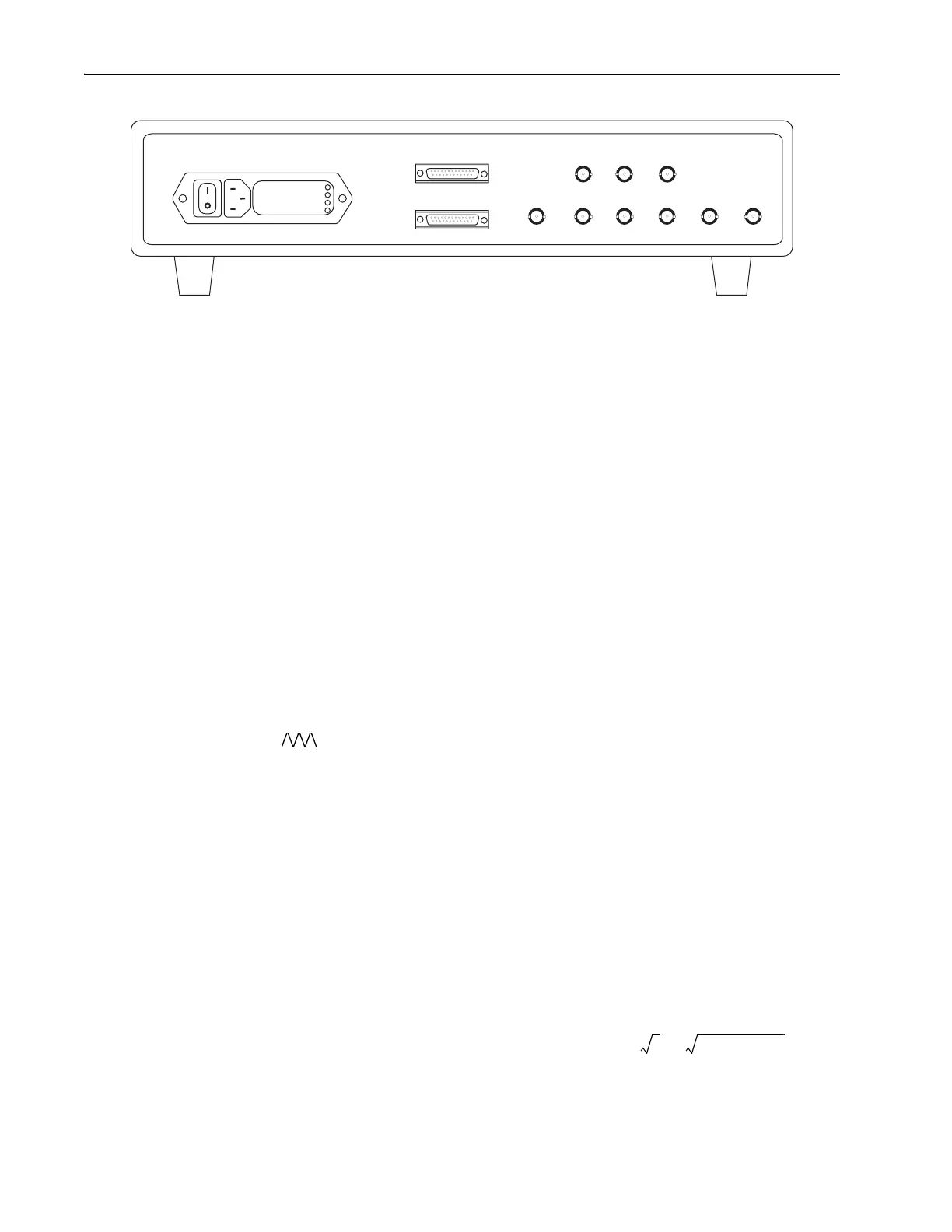
Figure 8-3: Model 3930 Electronics Module Rear Panel Controls and Connections
RS-232-C serial input (9-pin male)—connects to a standard RS-232-C con-
trol source for remote control of the Model 3930 and the Lok-to-Clock
functions. Refer to “Lok-to-Clock Computer Interface” in the second half
of this chapter for detailed information on the use of this connection. Also
available is a PC-based LabView interface that also uses this connector.
Refer to Appendix D for information on the use of the LabView software.
TO HEAD main signal D-sub connector (25-pin female)—connects to
the female 25-pin TO 3930 connector on the Tsunami laser head input
bezel.
EXT TIMING ADJUST connector—provides connection for an external
error input signal (supplied by user). Input impedance is 20 kΩ. Signal sen-
sitivity is approximately 7.5
mV
/ps. This signal is summed with the signal
from the coarse and fine TIMING controls (Figure 8-4).
LOOP MONitor connector—provides a buffered feedback signal for mon-
itoring the system using an oscilloscope or volt meter. The best system per-
formance is achieved when the laser is adjusted for the smallest output
signal. Output impedance is 1 kΩ. Signal sensitivity is approximately
100
mV
/ps. Output voltage range is approximately ±15 V.
OUT connector—provides a fixed, buffered, 10 Hz triangle wave
from the internal sweep generator that can be used to drive the horizontal
sweep on an oscilloscope (it provides a synchronized timing function). The
signal is present even when the sweep generator is not selected on the front
panel. Output impedance is 1 kΩ.
PHOTODIODE OUT connector—provides a buffered Tsunami laser photo-
diode output signal for monitoring on an oscilloscope. Output impedance is
50 Ω at –10 dBm for a sine wave. dBm is dB with respect to one milliwatt.
For example:
–10 dBm = 200 mV
pp
0 dBm = 0.63 Vpp
10 dBm = 2 Vpp
To convert to watts: Watts =
To convert to volts, peak-to-peak:voltspp =
PHOTODIODE IN connector—attaches to the LT C P D photodiode output
connectors on the Tsunami laser input bezel. This feedback signal is used
by the Lok-to-Clock system to lock the Tsunami cavity to a set frequency.
Input impedance is 50 Ω at –10 dBm for a sine wave.
100V
120V
220V
240V
PHOTODIODE
OUT
PHOTODIODE
IN
REF
IN
REF
OUT
REF÷ 8
80 MHz
OUT
TO HEAD
RS-232-C
EXT TIMING
ADJUST
LOOP
MON
/\/\/\
OUT
0.001 10
dbm
10
-----------
⋅
22Watts 50⋅⋅⋅