Alignment
6-25
Converting Between Non-overlapping Optics Sets
The following procedure contains instructions for changing non-overlap-
ping optics sets. An IR viewer is required for this procedure.
Read the entire section before you begin conversion.
During this procedure, with the exception of P
1
and P
2
, which are the same
for either configuration, replace and align each optic one at a time, starting
with M
1
. Refer to Figure 6-17 or Figure 6-18 as you proceed. When you
replace the first optic with one from a different set, the laser will no longer
lase. Therefore, the system is aligned by referencing fluorescent spots, not
the laser beam. The spots will appear on each optic and on a card placed in
front of the output window.
All mirrors are registered on 3-point mirror seats for repeatability. The
exceptions are M
3
, where the overlap of M
3
and M
1
might change due to the
change in optics and/or different rotation orientations, and M
6
and M
9
,
where the wedge of the optic can change the plane of the reflected coating.
Note the part number printed on the barrel of the optic to verify the correct
optic is being installed. Optic descriptions and their part numbers are found
in the tables in Chapter 10, “Options and Accessories.”
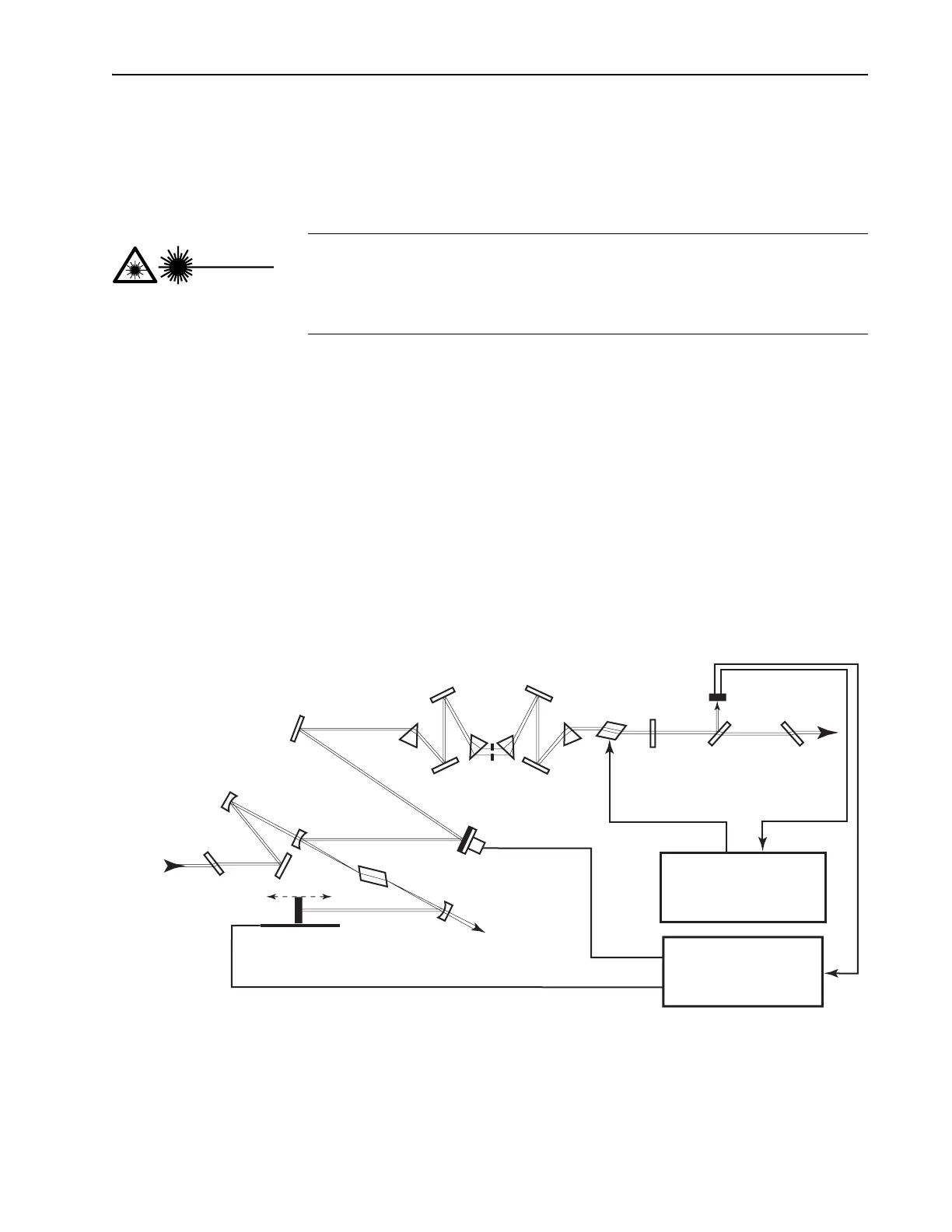
Figure 6-17: Tsunami fs Configuration.
This procedure requires you to replace optics while using the laser at
high power. For safety, close the pump laser shutter every time you
change an optic, and only open it during alignment. Protect yourself
with appropriate eyewear at all times.
Danger!
Laser Radiation
Output
Brewster
Window
Fast
Photodiode
Beam
Splitter
M
10
M
8
Pr
4
AOM
M
9
Pr
3
Pr
2
Tuning
Slit
M
6
Pr
1
M
7
M
5
P
2
M
3
M
4
PZT (optional)
Ti:sapphire Rod
P
1
M
2
Residual
Pump
Beam Dump
Motorized (optional)
Input
Brewster
Window
Pump
Beam
Model 3955
AOM Driver Electronics
Model 3930
Lok-to-Clock Electronics
Optional
HR
OC
M
1