Installation
5-9
5. Plug the GTI cable into connector J
2
on the pc board (Figure 5-4).
6. Connect the black, high-voltage, coaxial cable (provided with the GTI)
to the SMA connector at J
6
on the pc board.
Remove the red plastic cap from the SMA connector and attach the
screw-on end of the cable to the connector.
7. Route the coaxial cable along the side of the resonator and connect the
other end of the cable to the gold connector on the GTI. Push the con-
nector on until it snaps.
Do not allow the cables to interfere with any resonator mechanical
assemblies or the beam path.
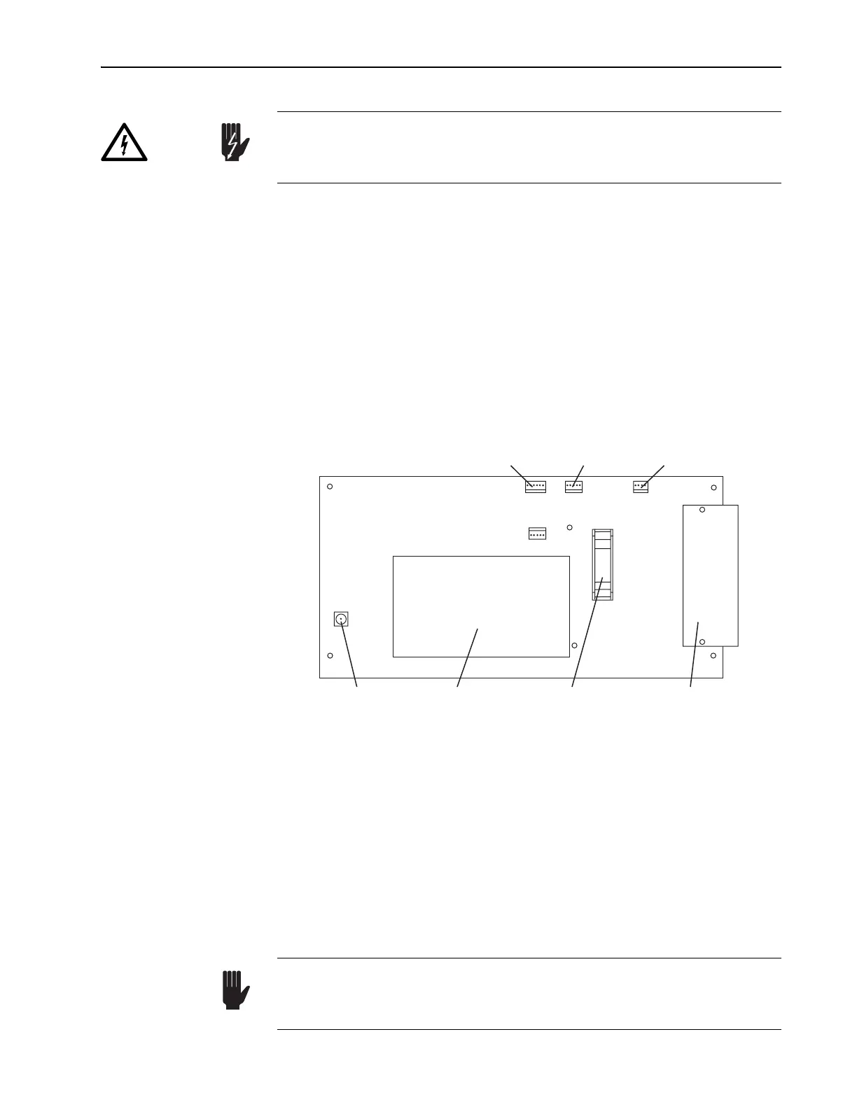
Figure 5-4: Tsunami Laser Head PC Board Connections
This completes the GTI installation.
Verifying Cable Connections
1. Verify the A/O modulator (AOM) heater cable is connected to J
3
on the
laser head pc board.
2. Verify a black coaxial cable is connected between the gold SMA con-
nector on the AOM and the ML mode locker connector on the inside of
the input bezel.
The pc board on the floor of the laser head normally contains high volt-
age. Verify the Model 3955 electronics module is off to insure this board
is disabled.
Danger!
J4
J2
J3
J5
J1
J6
Photodiode Board
Signal Connector
J
4
(6-Pin)
GTI Heater
Connector
J
2
(5-Pin)
Mode Locker
Heater Connector
J
3
(4-Pin)
High Voltage
GTI SMA
Connector J
6
High Voltage
Module for GTI
Head Control Panel
Signal Connector
J
5
(10-Pin)
Input Bezel
Signal Connector
J
1
(25-Pin)
Be careful when connecting the AOM and photodiode cables. Connect-
ing the AOM coaxial RF cable to the photodiode connector can cause
permanent damage to the photodiode pc board.
Warning!