Tsunami Mode-Locked Ti:sapphire Laser
8-2
trolled M
4
mirror. To this end, mirror M
1
is mounted on a motorized
micrometer that is controlled via the up/down buttons on the Model 3930.
The M
1
control is typically a manual coarse control, while M
4
is an auto-
matic fine control. However, if the difference between the reference and the
laser cavity frequency is < 50 kHz when the LOCK button is pressed, the
system will automatically servo the
M
1
motor micrometer in order to bring
the frequency difference within the locking range (< 100 Hz) of the
PZT-
controlled M
4
mirror. A bar graph indicator on the Model 3930 indicates the
relative position of M
4
so that you can tell when it is nearing its out-of-
range point.
The electronics module also provides controls and indicators for setting
and viewing the photodiode signal level and the reference frequency. A
built-in 10 Hz sweep generator can be used to create a 2 ns phase shift in
the Tsunami photodiode signal. This facilitates locating pulses when trying
to lock the LTC Tsunami to another laser.
An optional RS-232 serial interface is also available for controlling the LTC
functions from a remote source. The second half of this chapter is devoted
to its operation and command structure. A LabView interface that uses the
RS-232 port is also available and is explained in Appendix D. Specifica-
tions for the LTC system are at the end of this chapter.
System Controls
The following describes the displays and controls on the front and rear pan-
els of the Tsunami Model 3930 LTC electronics module.
Front Panel
TIMING coarse/fine control—sets the timing between the reference source
and the Tsunami laser. Both the coarse (outer knob) and fine (inner knob)
controls have a 10-turn resolution. The range for the coarse control is
approximately 2 ns; it is 100 ps for the fine control. When the sweep gener-
ator (see below) is off, the coarse/fine controls set the timing reference;
when the sweep generator is on, the coarse/fine controls are disabled.
TIMING sweep generator on/off push button—toggles the triangle wave
sweep generator on and off (default = off). The sweep runs at about 10 Hz,
and produces a linear timing change of about 2 ns. When the generator is
off, the coarse/fine controls set the timing reference; when on, the coarse/
fine controls are disabled.
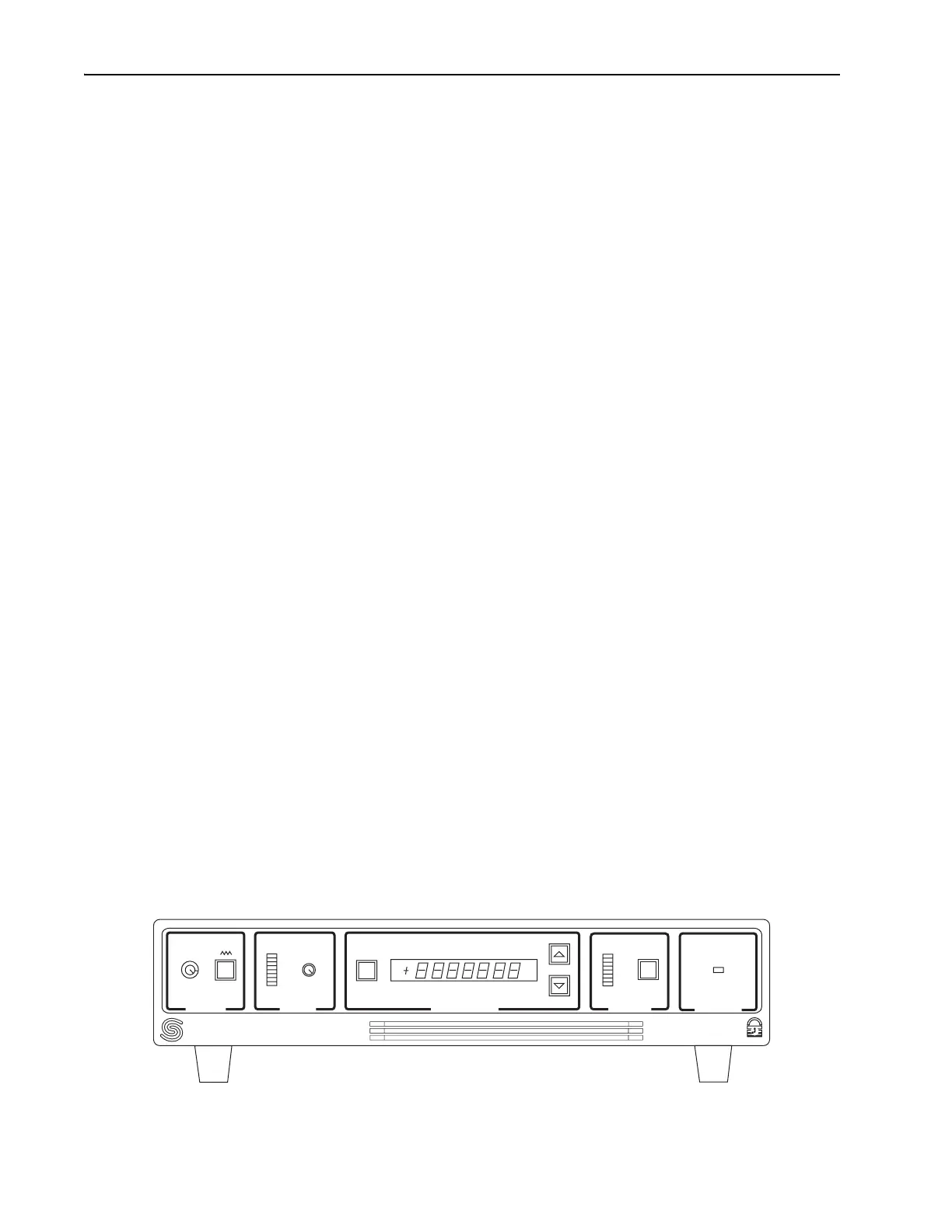
Figure 8-2: Model 3930 Electronics Module Front Panel Controls and Indicators
TIMING
LEVEL
FREQUENCY
STATUS
POWER
SELECT
LOCK
ON
Model 3930
REF
LSR
DIF
S p e c t r a - P h y s i c s