Controls, Indicators and Connections
4-3
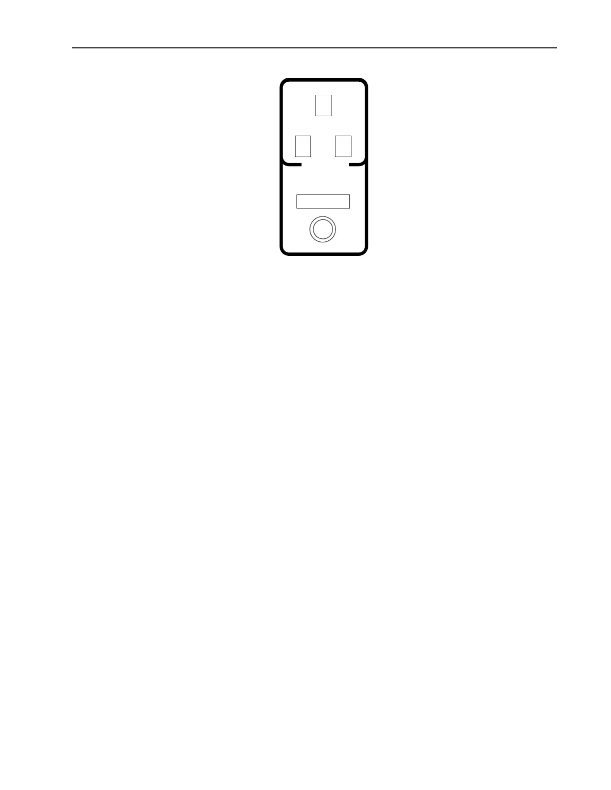
Figure 4-2: Tsunami Laser Head Control Panel
GTI TEMPERATURE indicator—when green, it indicates temperature has
stabilized; red indicates the opposite. It flashes red when no GTI is installed
(this is normal for fs configuration) or when its cable is left unplugged.
From a “cold” start-up, expect a stabilization time of about 15 minutes.
GTI POSITION display—indicates the relative position of the GTI disper-
sion control (ps configuration), or displays an arbitrary setting when no GTI
is installed (fs configuration).
GTI POSITION dispersion compensation control—optimizes the group
velocity dispersion (GVD) compensation for pulse length adjustment in ps
systems, and is inactive when no GTI is installed (fs configuration).
Mechanical Controls
Shutter—blocks the pump beam at the entrance to the Tsunami laser head
housing to prevent the Tsunami from lasing. When the cover is in place, it
holds the shutter open for normal operation. When it is removed, the shut-
ter closes automatically, blocking the input beam. The shutter can be
defeated (opened) when the cover is off by pulling up on the red-tipped
lever until the lever is in the full upright position (Figure 2-3). In this posi-
tion, the lever prevents the cover from being properly installed, and
reminds the user to reset the shutter before closing up the laser head.
Foot height adjustment—two on the input end and one on the output end
allow the laser head height to be adjusted to the height of the pump laser
input beam. The legs are large screws with swivel feet that can be screwed
up and down from inside the laser using a
5
/32 in. Allen (hex) driver. Once
adjusted, jam nuts on the legs are tightened against the bottom of the base
plate to secure the set position and provide mechanical stability.
Cover clamps—one on each corner of the base plate, secure the cover in
place. To release the cover, pull outward on the bottom of each of the four
cover latches until it snaps. Then, while pressing downward on the cover to
release the pressure on the latches, pull the top portion of the latch away
from the notch in the cover. Perform the opposite to latch the cover.
STATUS
PULSING
GTI
TEMPERATURE
MODE LOCKER
TEMPERATURE
GTI POSITION