Operation
7-3
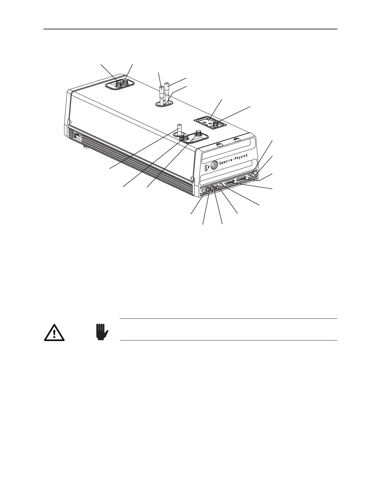
Figure 7-2: Tsunami External Laser Head Controls
c. Set the output regulator to limit pressure to less than 67 kPa (10 psi).
d. Open the Tsunami purge bleed valve (Figure 7-2).
e. Use the Model 3910 flow control (Figure 4-9) to set the nitrogen
flow rate as outlined above.
Optimizing Laser Output
1. Place a power meter in front of the Tsunami output window.
2. Open the pump laser shutter. The Tsunami laser should begin lasing if
it was not adjusted since the last time it was used.
3. Adjust
M
10
and M
1
(Figure 7-2) for maximum output power and note
the power level.
You can often increase output power a little more by “walking the
beam.” The following procedure may improve the overlap of the cavity
beam and the pump beam in the rod.
4. Slightly detune
M
1
vertically (power will decrease). Note the direction
you turned the control.
Output Coupler (M
10
)
Horiz. Vert.
Prism Dispersion
Compensation Control (fs)
Slit Wavelength Selector (fs)
Slit Bandwidth Selector (fs)
Laser Head Control Panel
GTI Dispersion
Compensation Control (ps)
Mode Locker Photodiode
(ML PD) Connector
Mode Locker (ML)
Connector
Model 3955 (TO 3955)
Signal Connector
Model 3930 (TO 3930)
Signal Connector
LTC Photodiode (LTC PD)
Connector
Purge Inlet Connector
Water Outlet Connector
Water Inlet Connector
Purge Bleed Valve
Horiz. Vert.
M
1
GTI (ps) or High Reflector (fs)
Birefringent Filter
Wavelength Selector (ps)
Blue: Vertical Adjust
Green: Horizontal Adjust
Caution!
Direct back reflections into the oscillator can cause serious instabilities
in laser performance. Please take precautions to avoid such reflections.