Modelocking
A-5
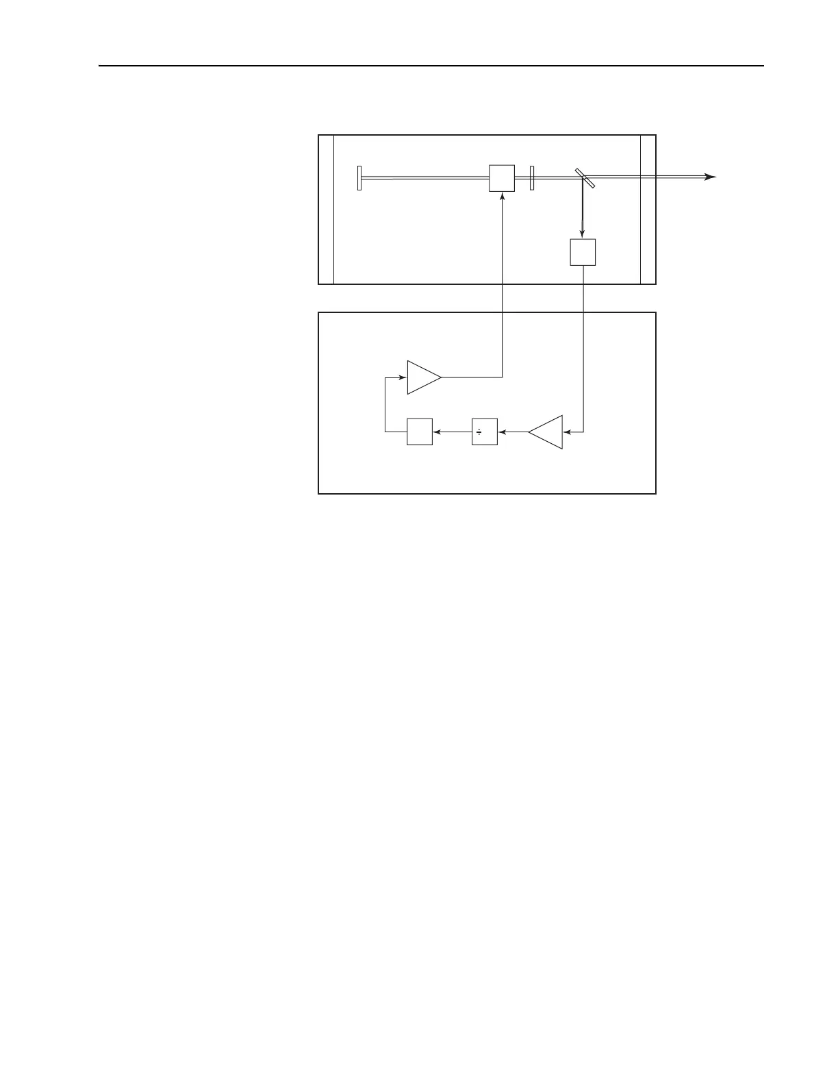
Figure A-4: Configuration of the electronics for a regenerative mode-
locked laser.
Group Velocity Dispersion (GVD)
Fourier analysis (or as consequence of the Heisenberg uncertainty princi-
ple) imposes a restriction on the bandwidth of an ultrashort pulse. For a
pulse of duration
∆
t
p
and bandwidth
∆ν
, it is always true that
∆ν
@∆t
p
will
be greater than a constant with a value of about 1. The exact nature of the
constant depends on the exact shape of the pulse (examples are given in
Appendix B). It is apparent that, the shorter the pulse, the larger the band-
width and, thus, the greater the difference from the lowest to highest fre-
quency within a pulse. Since the index of refraction of any material is
frequency dependent, each frequency in a pulse experiences a slightly dif-
ferent index of refraction as it propagates. This index of refraction differ-
ence corresponds to a velocity difference, causing a time separation
between the different frequencies of a pulse. Group velocity dispersion
(GVD) is defined as the variation in transit time as a function of wave-
length. For positive GVD, the lower frequencies (red) travel faster than
higher frequencies (blue). The effect is more pronounced for shorter pulses
(because of their larger bandwidth).
Figure A-5 shows the refractive index n versus wavelength
λ
for a typical
transparent optical material. For any given wavelength, the refractive index
n(
λ
) determines the phase velocity. The slope of the curve, dn(
λ
)/d
λ
, deter-
mines the group velocity, or the velocity of a short pulse with a center
wavelength of
λ
..
Photo-
diode
2
Modulator
Driver Amplifier
Phase
Adjust
Divider
Photodiode
Amplifier
Beam SplitterAOMHR
OC
Output
Beam
Tsunami
Model 3930
∆φ