Controls, Indicators and Connections
4-9
Fine PHASE control—adjusts the phase relationship between the AOM
signal and the photodiode signal to provide a pulse-locking mechanism. Its
adjustment range is about 100 ps. Adjust this control to sync the mode
locker to the pulse rate.
NOTE: If you use cables other than those shipped with the system, or if you
convert from a ps to a fs configuration, or vice versa, or convert from extra-
long (X) to standard (S) wavelength, or vice versa, the phase signal may
move outside the 100 ps range of this control. If this happens, you need to
adjust the coarse control located on the Main pc board inside the Model
3955. Refer to “Coarse Phase Adjustment...” at the end of Chapter 6.
POWER: ON indicator—indicates power is applied to the Model 3955
electronics module, the
AOM heater and GTI heaters, and that high voltage
is applied to the
GTI. The GTI is present only in the ps configuration.
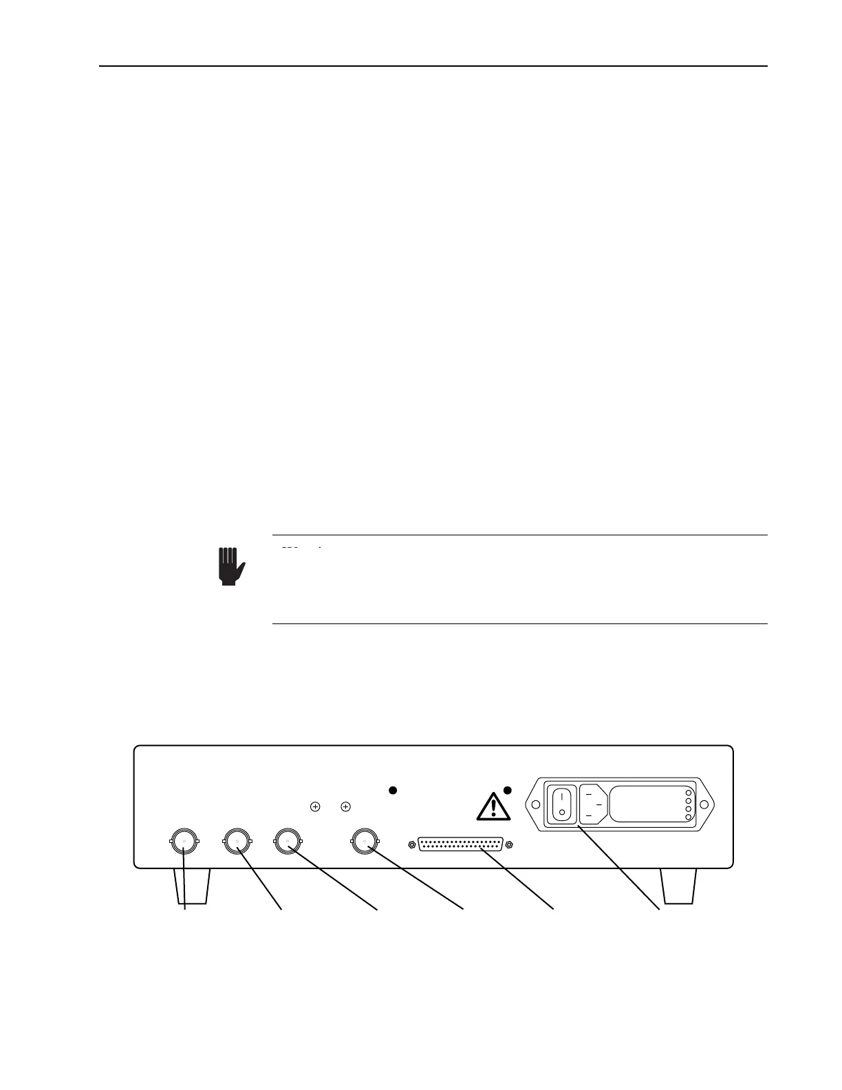
Rear Panel
The following is a description of the connections and switches on the
Model 3955 rear panel. Refer to Figure 4-6.
PHOTODIODE BNC connector—receives the control signal from the laser
head photodiode. It attaches to the ML PD photodiode connector on the
right side of the laser head input bezel. Use the MONITOR connector on the
rear panel to monitor this signal on an oscilloscope or frequency counter.
Use the SYNC output (sine wave) to trigger the oscilloscope.
MONITOR BNC connector—connects to a frequency counter or to a 50 Ω
oscilloscope input for monitoring the laser head photodiode signal. A typi-
cal waveform is shown in Figure 4-7. Use the SYNC output (sine wave) to
trigger the oscilloscope. The signal amplitude shown is approximate and
depends on operating wavelength, power and photodiode response.
Figure 4-6: Model 3955 Electronics Module Rear Panel Controls and Connections
Warning
Warning!
Do not attach the ML PD photodiode connector to the LTC PD connector!
The three BNC connectors on the laser head provide different output
signal levels that can damage the receiving device if they are connected
to the wrong receiver.
100V
120V
220V
240V
PHOTODIODE
MONITOR
SYNC MODE LOCKER
TO HEAD
Photodiode
Connector
Monitor
Connector
Sync
Connector
Mode
Locker
Connector
Main Signal
Connector
To Head
Power Line
Connector and
On/Off Switch