Alignment
6-9
h. Remove the white card and place it about 10 cm outside the output
window.
i. Adjust
M
5
to direct the fluorescent spots through the AOM, through
M
10
and onto the card. The spots should be centered in the back-
ground scatter that is shaped by the
AOM and M
10
.
An IR viewer may be required in order to view the small, cross-
shaped image centered in the background scatter on the white card
(Figure 6-6). If the image is absent, it may be blocked by one or
both of these components. Place another white card between the
AOM and M
10
and, using it as a knife edge and slowly moving it
into the fluorescent spots, detect the position of the beam relative
to the two components and properly center it on M
10
.
j. Remove the white card.
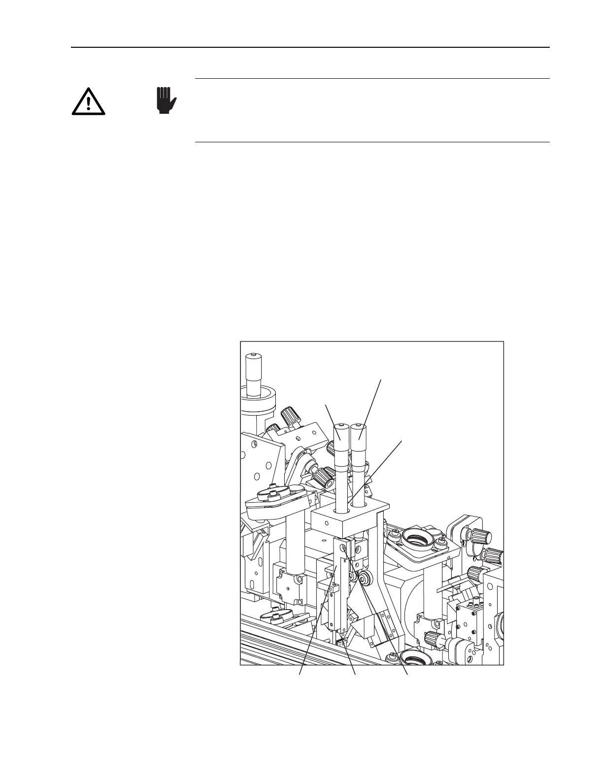
Figure 6-8: The Slit Control
Do not place the card between the optical components from M
6
to M
9
.
The refraction of fluorescence through the prisms causes the spots to
spread in the vertical plane and, thus, are not representative of the laser
beam path. DO NOT adjust M
6
through M
9
, nor the prism angles.
Caution!
Tuning Slit
Assembly
Slit Capscrew
Slit
Wavelength
Selector (fs)
Micrometer
Prism Dispersion
Compensation Control (fs)
Slit
Bandwidth
Selector (fs)