Alignment
6-31
adjust the vertical controls for mirrors M
6
, M
7
, M
8
and M
9
to reposition the
beam properly on the prisms. Lasing should resume when the last vertical
adjustment is made.
Once the beam is properly positioned on the prisms, the prisms themselves
must be adjusted to provide the right amount of GVD compensation for the
wavelength range selected. It is the amount of prism glass exposed to the
laser beam that determines the amount of GVD compensation added to the
system. In general, the blue range requires the most prism glass to mini-
mize the pulse width. Thus, when converting from blue or standard to long
or x-long, or vice versa, Pr
1
and Pr
4
must be adjusted according to Table 6-6
and Figure 6-22 to provide the proper amount of glass in the cavity beam.
1. Adjust the vertical controls on
M
6
through M
9
(top screw) according to
Table 6-5 to reestablish the correct beam position on prisms
Pr
2
and Pr
3
.
The prism type can be identified by the apex angle written on it:
SF-10: 60° 40’
LaFN28: 59° 12’
2. Adjust prisms Pr
1
and Pr
4
according to Table 6-6 and Figure 6-22 for
proper GVD compensation. Small holes in the beam shields provide
access to the drive screws.
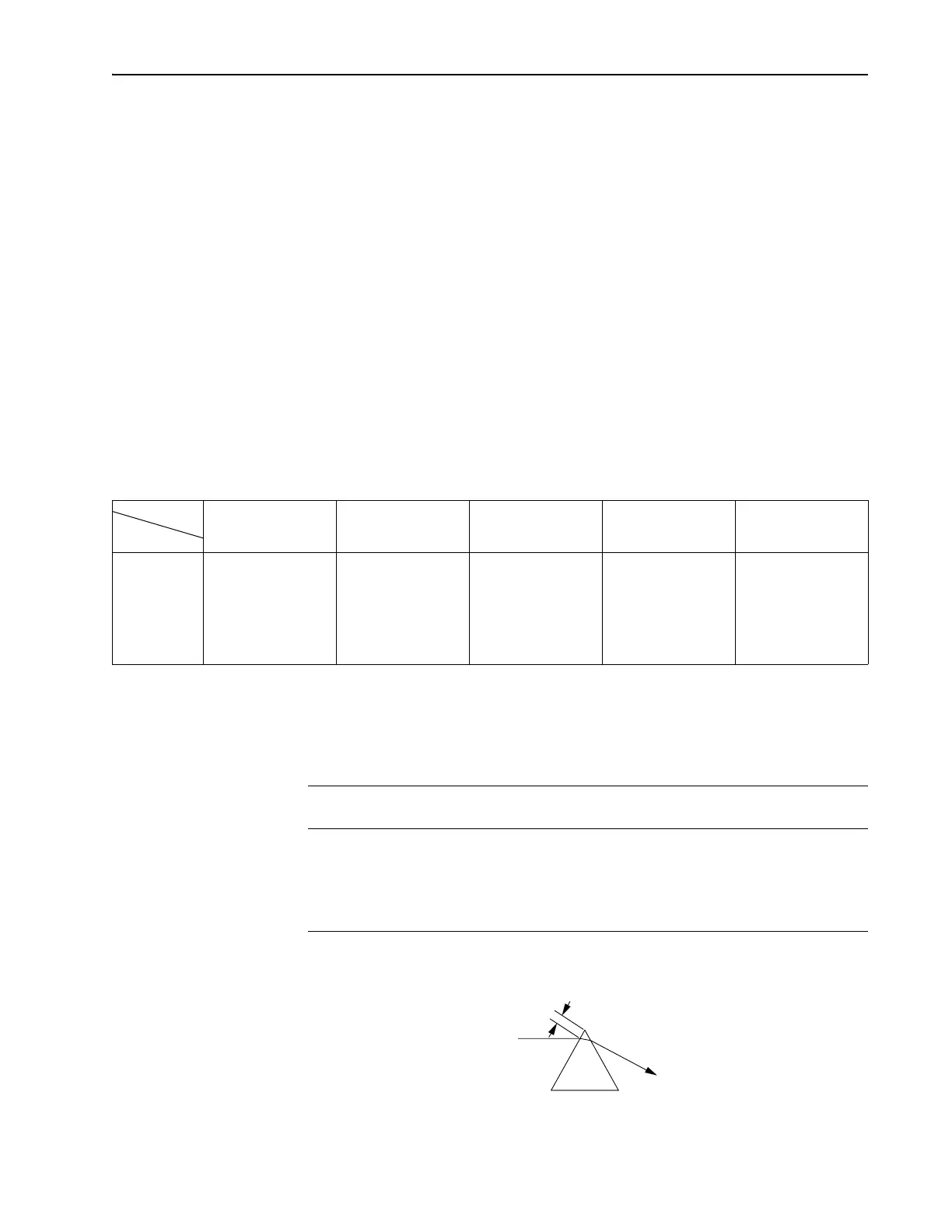
Figure 6-22:
Pr
1
/Pr
4
prisms showing placement of beam. Refer to Table
6-6 for the value of x.
Table 6-5: Vertical Mirror Adjustment (Turns) for Changing Wavelengths
Blue Std./Mid. Long X-Long Broadband
SF-10 LaFN28 SF-10 LaFN28 SF-10 LaFN28 SF-10 LaFN28 SF-10 LaFN28
Blue NA NA 1½ ccw NA 3 ccw NA 3 ccw 1 ccw NA NA
Std./Mid. 1½ cw NA NA NA 1½ ccw NA 1½ ccw 1 ccw NA NA
Long 3 cw NA 1½ cw NA NA NA NA 1 ccw NA NA
X-Long 3 cw 1 cw 1½ cw 1 cw NA 1 cw NA NA 1½ cw 1 cw
Broadband NA NA NA NA NA NA 1½ ccw 1 ccw NA NA
Table 6-6: Nominal Distance from Beam to Apex (see Figure 6-22)
Wavelength Range Pr1/Pr4 Center of beam to apex (x) with beam
centered on M
5
and M
10
SF-10 LaFN28
Blue 4–5 mm 3–4 mm
Std/Mid/Long/Broadband 3–4 mm 2–3 mm
X-Long
1
1
For X-Long, ensure the beam is not clipped by prism edges of Pr
1
and Pr
4
.
< 1 mm (as close as possible without clipping
To
From
x