Tsunami Mode-Locked Ti-sapphire Laser
6-10
3. Align M
10
.
a. Place a power meter in the Tsunami output beam path as a beam
block.
b. Place a white card with a 2.5 mm diameter hole in it between M
4
and M
5
so the hole is centered on the reflected fluorescent image
from
M
4
.
c. Direct the reflected image from
M
10
back through the hole in the
card and overlap it with the image coming from
M
4
.
To determine which reflected image comes from
M
10
, watch the M
5
side of the card and slightly adjust M
10
until you see which image
moves.
d. Remove the card; lasing should begin.
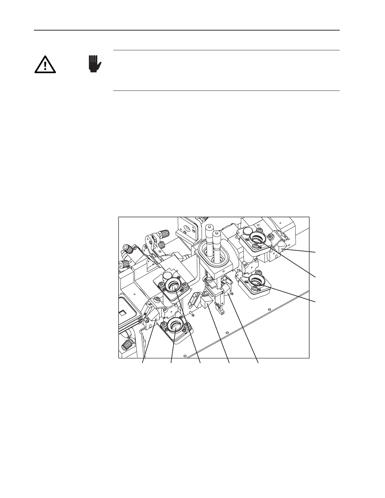
Figure 6-9: Four Prism/Four Mirror Section of fs Laser Cavity
4. Adjust M
10
and M
1
for maximum output power.
a. Adjust the vertical axis of
M
10
and M
1
for maximum output power.
Slightly rotate M
10
clockwise and optimize output power by adjust-
ing
M
1
. If power increases, continue the same direction, otherwise
reverse direction until power is maximized.
b. Repeat, using the horizontal controls.
c. Iterate these two steps to obtain maximum power in both axis.
DO NOT remove or adjust mirrors M
6
, M
7
, M
8
, or M
9
, or the prisms (Fig-
ure 6-9). These optics are prealigned at the factory and are not to be dis-
turbed unless specifically told to do so elsewhere in this manual. A
service call may be required if disturbed.
Caution!
Prism
Pr
1
Mirror
M
6
Mirror
M
7
Prism
Pr
2
Prism
Pr
3
Prism
Pr
4
Mirror
M
8
Mirror
M
9