Controls, Indicators and Connections
4-11
Power cord connector—connector for a standard line cord to attach the
Tsunami electronics to facility line power. (It is part of the power switch
assembly.)
Power switch—turns power on and off to the Model 3955 and the Tsunami
electronics located in the laser head. It is located next to the power cord
connector.
Voltage select switch—provides the means to match the electronics input
power to your facility line voltage. Input voltage selections are 100, 120,
220, and 240 Vac. Appendix C describes how to set the switch and select
the fuse rating for your location.
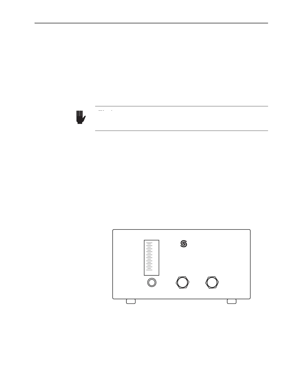
Model 3910 Purge Unit Controls
The Model 3910 contains oil and air filters and a molecular-sieve assembly
to dry and clean nitrogen gas for purging the Tsunami laser head. It has one
control and two connectors. Refer toFigure 4-9.
FLOW ADJUST knob—used to set the laser head purge rate (gas flow)
from 0.3 to 3.0 m
3
/hr (1.0 to 10.0 SCFH).
Flow adjust indicator—displays the nitrogen gas flow rate.
OUTPUT connector—connects the Model 3910 to the laser head to pro-
vide dried, filtered, nitrogen gas.
INPUT FROM GAS CYLINDER connector—connects the Model 3910 to a
dry nitrogen gas supply. Limit the input pressure to 67 kPa (10 psi).
Figure 4-9: Model 3910 Regulator/Filter Purge Unit
Warning
Warning!
Verify the voltage select switch is set to match the ac line voltage of
your facility. An improper selection will damage the electronics. Refer
to Appendix C for information on changing the setting.
FLOW ADJUST
OUTPUT
10 PSI MAX
INPUT FROM
GAS CYLINDER
SCFH
2
4
6
8
10
Spectra-Physics