Alignment
6-29
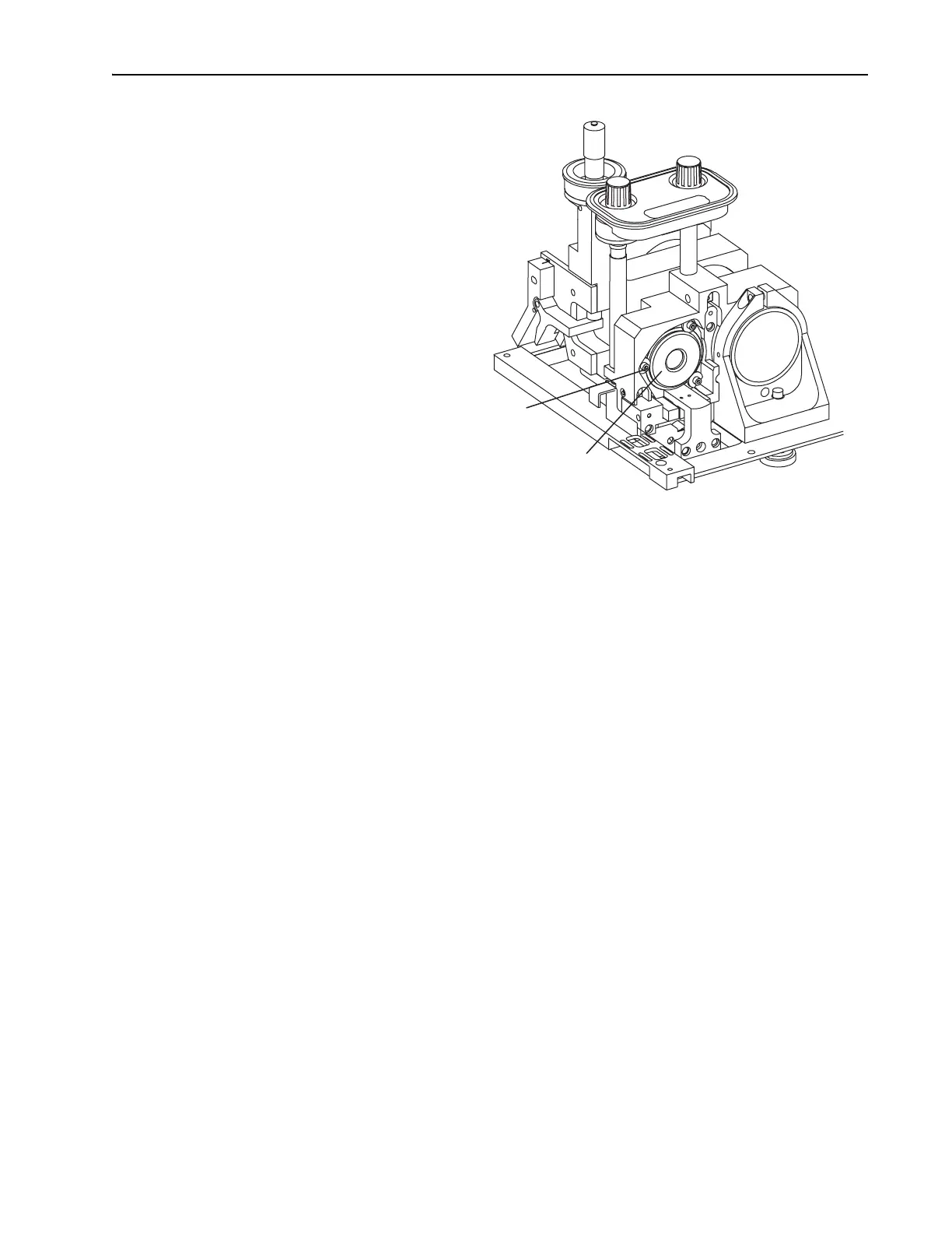
Figure 6-21: The Gires-Tournois Interferometer (GTI). The input bezel
and side rail are removed for clarity and the motorized mount shown is
available only on Lok-to-Clock systems.
d. Loosen the three screws holding the GTI to the rear mirror plate,
and turn the 3 D-shaped cam locks so the flat portion of the cam
disengages the GTI mounting ring (Figure 6-21).
e. Slide the GTI out of the mirror plate and remove it from the laser
head, pulling the gray heater cable through the mounting hole.
Take care not to snag it on anything. Store the GTI in its box.
f. Slide the appropriate GTI for the chosen wavelength into the mirror
plate, pulling the gray heater cable through first. Then rotate the
GTI so the gold connector is accessible for attaching the black
coaxial control cable to it.
g. Rotate the 3 cam locks so they capture the
GTI mounting ring, and
tighten the screws.
h. Connect the black coaxial control cable to the gold connector on
the
GTI, and push it in until it snaps.
i. Route the GTI heater cable along the side of the resonator, from the
GTI to the laser head pc board, then plug it into connector J
2
on the
pc board.
j. Turn on the Model 3955 electronics module. It will take about 20
minutes for the GTI heater to warm up, but you can continue with
this procedure.
8. Place a white card in front of
M
5
.
9. Adjust M
1
vertically and horizontally to overlap the two fluorescent
images from M
1
and M
3
that are displayed on the card and create a
cross-shaped image.
GTI or HR Motorized Mount
Mounting Screws with
"D"-shaped Cam Locks (3)