Tsunami Mode-Locked Ti:sapphire Laser
5-8
1. Remove the GTI from its shipping container and inspect it for damage.
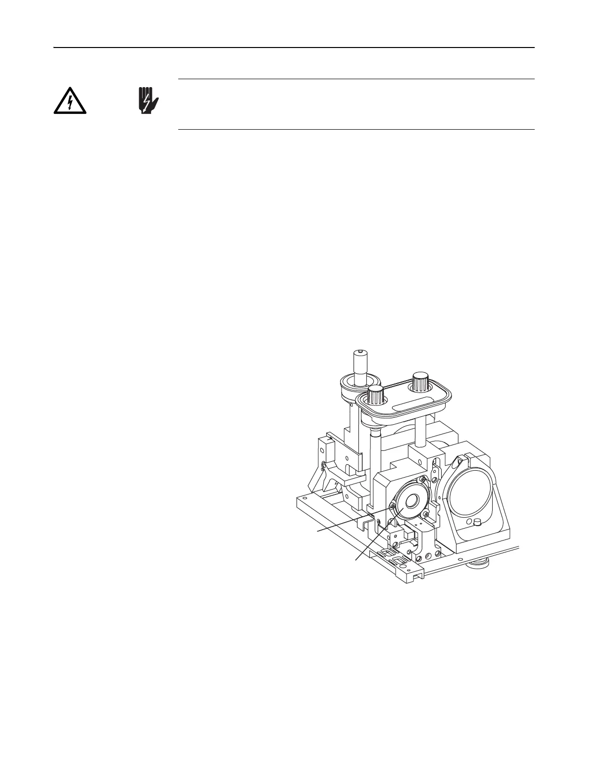
2. Install the GTI into the laser head (Figure 5-3).
The
GTI installs into the M
1
mirror plate from the input bezel side.
a. Turn the D-shaped cam lock washers under the three screws so the
flat sides face the mounting hole and permit the
GTI to slide in.
b. Pull the gray cable from the GTI through the mounting hole first
before installing the GTI.
c. Set the GTI into the mounting hole, and push it all the way in until
the shoulder ring seats against the mount.
d. Rotate the GTI so the gold connector is near the bottom. A cable
will be attached later.
e. Turn the cam locks around so the round portion of the washer cap-
tures the GTI shoulder ring, and tighten the screws.
Figure 5-3: The Gires-Tournois Interferometer (
GTI). The input bezel
and side rail are removed for clarity and the motorized mount shown is
available only on Lok-to-Clock systems.
3. Route the gray
GTI cable along the side of the resonator, from the GTI
to the pc board located on the floor near M
4
.
4. Remove the plastic cover protecting the pc board (3 screws).
The pc board on the floor of the laser head contains high voltage for
driving the GTI. Verify the Model 3955 electronics module is off to dis-
able this board before continuing.
Danger!
GTI or HR Motorized Mount
Mounting Screws with
"D"-shaped Cam Locks (3)