4-1
Chapter 4 Controls, Indicators and Connections
Introduction
This section defines the user controls, indicators and connections of the
Tsunami
®
laser system. It is divided into three sections: the Tsunami laser
head, the electronics module, and the Model 3910 purge unit. Information
on the chiller can be found in the user's manual that accompanies the
chiller. The optional Model 3930 Lok-to-Clock
®
electronics module is cov-
ered in Chapter 8.
Figure 4-3 and Figure 4-4 are large fold-out diagrams of the Tsunami laser
head that show its many internal components and controls.
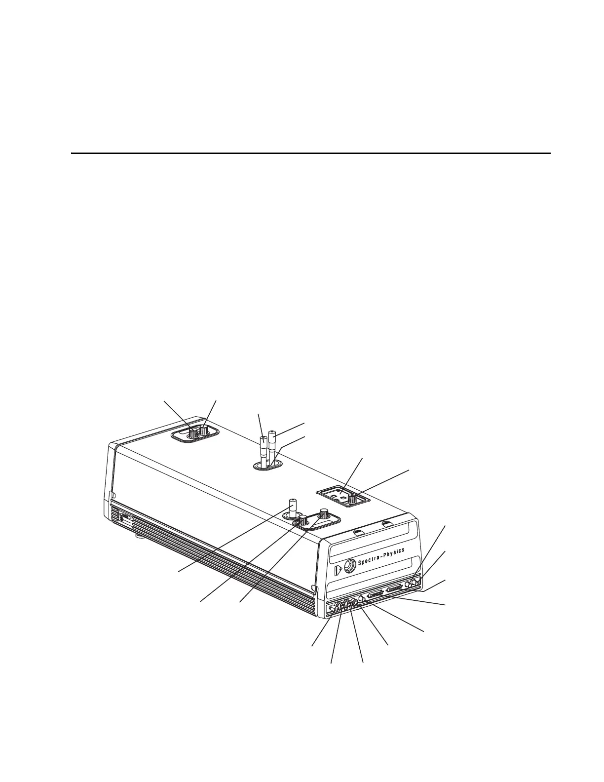
Laser Head Controls
Figure 4-1: Tsunami external laser head controls. Not all controls are present on some models.
Output Coupler (M
10
)
Horiz. Vert.
Prism Dispersion
Compensation Control (fs)
Slit Wavelength Selector (fs)
Slit Bandwidth Selector (fs)
Laser Head Control Panel
GTI Dispersion
Compensation Control (ps)
Mode Locker Photodiode
(ML PD) Connector
Mode Locker (ML)
Connector
Model 3955 (TO 3955)
Signal Connector
Model 3930 (TO 3930)
Signal Connector
LTC Photodiode (LTC PD)
Connector
Purge Inlet Connector
Water Outlet Connector
Water Inlet Connector
Purge Bleed Valve
Horiz. Vert.
M
1
GTI (ps) or High Reflector (fs)
Birefringent Filter
Wavelength Selector (ps)
Blue: Vertical Adjust
Green: Horizontal Adjust