Tsunami Mode-Locked Ti-sapphire Laser
6-26
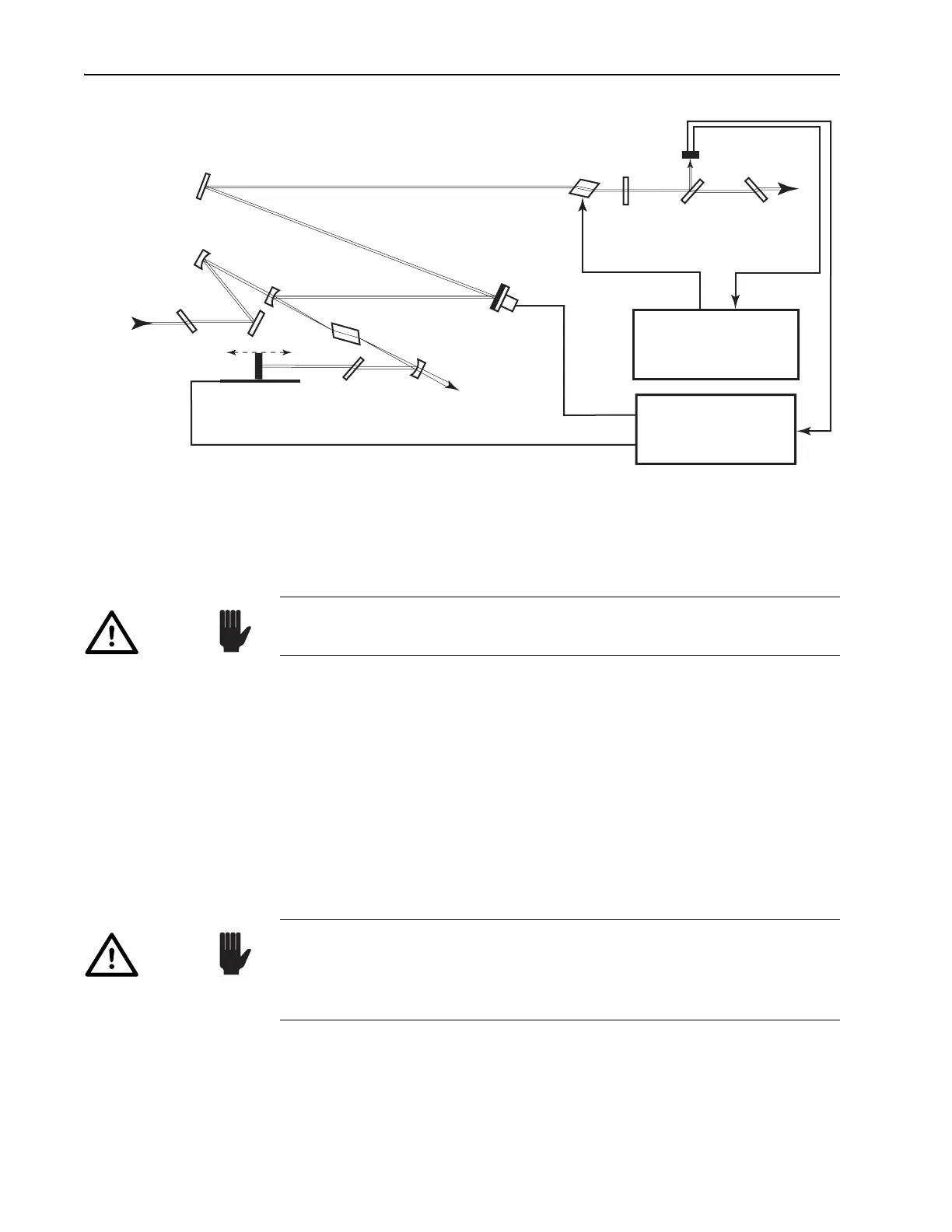
Figure 6-18: Tsunami ps Configuration.
Unless you are certain the new optics are clean, clean each one as it is
placed in the laser. Refer to Chapter 9, “Maintenance,” for cleaning proce-
dures.
To observe the intracavity fluorescence throughout the following proce-
dure, place a white card about 10 cm outside the laser output port.
After each optic is replaced and adjusted, verify the fluorescent cross cre-
ated in Step 9 below is still evident on the white card. It is important the
steps below be followed in sequence and that each is completed before
starting the next step. The laser will not lase until every optic is replaced
with optics from a single set. If you cannot get the system to lase and you
feel the cavity is misaligned, install the standard optics set (which is easier
to get lasing) and refer to the cavity alignment procedures earlier in this
chapter to check the alignment of the system. Once the system lases, repeat
this procedure.
1. Turn off the AOM by pressing the STATUS mode locker enable button
on the Model 3955.
2. Verify the beam is centered on
M
1
, M
4
, M
5
and M
10
.
Output
Brewster
Window
Fast
Photodiode
Beam
Splitter
M
10
AOM
M
5
P
2
M
3
M
4
PZT (optional)
Ti:sapphire Rod
P
1
M
2
Residual
Pump
Beam Dump
Motorized (optional) Birefringent
Filter
Input
Brewster
Window
Pump
Beam
Model 3955
AOM Driver Electronics
Model 3930
Lok-to-Clock Electronics
Optional
HR
OC
M
1
Always use clean finger cots or powderless gloves when handling
optics.
Caution!
Verify the Tsunami meets specified power for the installed optic set
before changing optic sets. Refer to Chapter 7, “Operation: System
Start-up,” and to the specifications listed in the tables at the end of
Chapter 3.
Caution!