Tsunami Mode-Locked Ti:sapphire Laser
4-8
Opto-Mechanical Controls
ps Configuration
The following describes the opto-mechanical controls present on Tsunami
lasers that are configured for picosecond only operation (Model 3950) or
on femtosecond systems designed for conversion to picosecond operation
(Model 3960). Refer to Figure 4-3 and Figure 4-4.
M
1
Gires-Tournois interferometer (GTI)—compensates for dispersion
and can be adjusted for shortest output pulse. The GTI replaces the HR that
is used in the fs configuration. Its vertical and horizontal adjustments allow
you to align the laser cavity and to optimize output power and mode qual-
ity. These controls are accessible when the laser head cover is in place.
Birefringent filter (bi-fi) wavelength selector—selects the laser wave-
length. Its micrometer control is accessible when the laser head cover is in
place.
Model 3955 Electronics Module Controls
Front Panel
The following is a description of the displays and controls on the front
panel of the Model 3955. Refer to Figure 4-5.
PHOTODIODE indicator—displays relative photodiode signal strength
with full-scale = maximum signal. This is an uncalibrated reference indica-
tor.
STATUS: PULSING mode locker indicator—when lit, it indicates the
system is mode locked. When off, it indicates no pulses are detected.
STATUS: ENABLE mode locker indicator—when lit, it indicates mode
locking is enabled.
STATUS mode locker enable/disable button—turns on or off RF power
to the AOM. Note: even when RF power is off, power to the heater is still
applied.
PHASE display—indicates the relative position of the fine PHASE control.
This is an uncalibrated reference indicator.
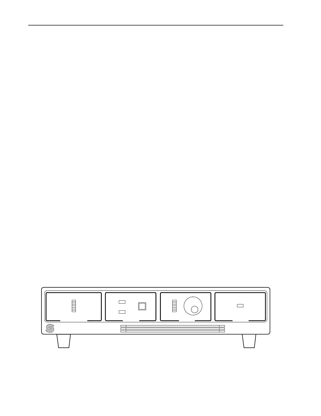
Figure 4-5: Model 3955 Electronics Module Front Panel Controls and Indicators
Model 3955
PHOTODIODE STATUS PHASE POWER
PULSING
ENABLE
ON