Tsunami Mode-Locked Ti-sapphire Laser
6-12
Aligning the A/O Modulator (AOM)
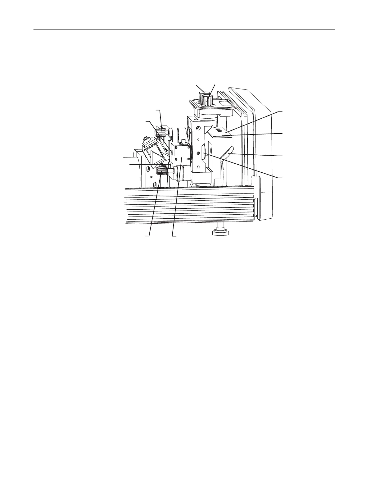
Figure 6-10: AOM, Output Coupler, Photodiode PC Board, and Beam Splitter
The photodiode pc board must be aligned before you align the AOM. This
assures a maximum photodiode signal for reliable modelocking. Refer to
“Aligning the Photodiode PC Board” later in this chapter.
If you have not already done so, perform the “Test for Proper Modelock-
ing” later in this chapter before you attempt this alignment. If the laser
modelocks properly, you do not have to perform this procedure.
1. Verify the output beam is centered on M
10
.
Place a white card between
M
10
and the beam splitter, and use the edge
of the card to detect the position of the beam.
2. Use the vertical control knob of M
10
to detune the laser until it stops
lasing.
3. Verify the intracavity beam is centered in the AOM.
Use an IR viewer to see that the
M
3
/M
1
fluorescence is centered through
the silhouette of the AOM crystal. The fluorescence should not be near
the edges of the crystal. If necessary, loosen the
AOM mounting
bracket to adjust it vertically and horizontally. Two
2-56 setscrews hold
it horizontally while two
9
/64 in. cap screws keep it secured vertically.
4. Readjust M
10
vertically to reestablish lasing and to optimize output.
Output Coupler (M
10
)
Positioning Controls
Horz. Vert.
Photodiode
PC Board
Mounting
Screws (2)
Beam
Splitter
Output
Coupler (M
10
)
AOM Pitch Control
AOM Aperture Window
AOM Mounting Setscrews (2)
AOM Horizontal
Angle Control
AOM