Tsunami Mode-Locked Ti-sapphire Laser
6-8
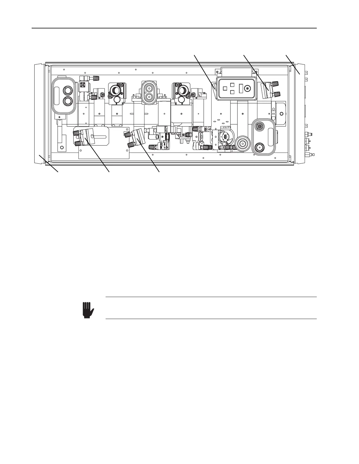
Figure 6-7: Locations of M
4
and M
5
for fs operation.
2. Align fold mirrors M
4
and M
5
.
a. Verify M
4
and M
5
are in their correct positions for fs operation (Fig-
ure 6-7).
b. Adjust M
3
to center the fluorescence on M
4
.
Take into account the horizontal positional offset of M
4
by placing
the beam horizontally
2
/3 the distance from the center of the plate.
c. Adjust M
4
to center the reflected images from M
3
and M
1
onto M
5
.
Take into account the horizontal positional offset of M
5
by placing
the beam horizontally
1
/3 the distance from the center of the plate.
d. Remove the slit assembly.
Loosen the screw holding the slit assembly to the spindle of the
control micrometer, then slide the slit down and off the micrometer
shaft (Figure 6-8).
e. Lower prisms
Pr
2
and Pr
3
to the bottom of their travel to intercept
all the fluorescence for ease of alignment.
f. Place a white card in front of the input to the A/O modulator
(AOM).
g. Using an IR viewer, adjust
M
5
so that the fluorescent spots go
through the prism sequence Pr
1
through Pr
4
and are displayed on
the white card.
Output Bezel M
4
ps Position M
4
fs Position
M
5
fs Position M
5
ps Position Input Bezel
Support the slit assembly with your hand when loosening the screw to
prevent it from falling off the shaft and damaging the optics below.
Warning!