Alignment
6-15
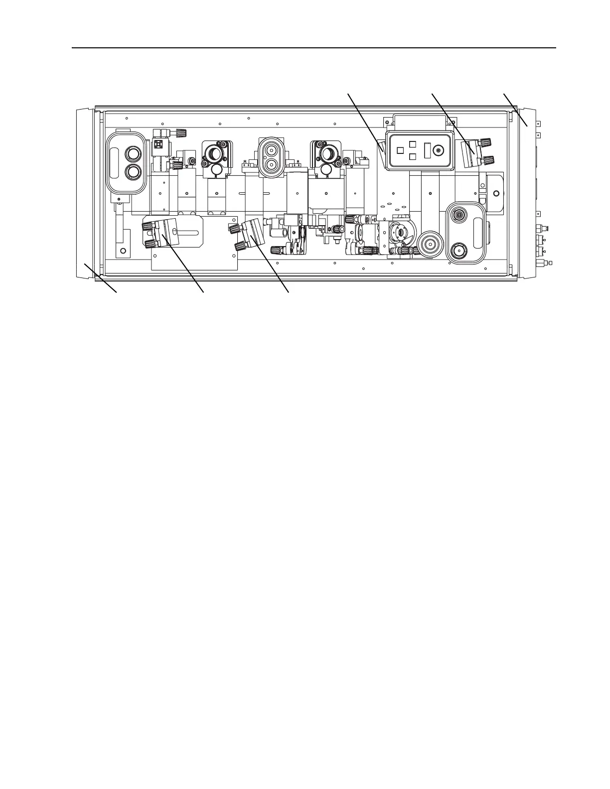
Figure 6-12: Locations of M
4
and M
5
for ps operation.
g. Adjust M
5
to direct the fluorescent spots through the AOM, through
M
10
, and onto the card. The spots should be centered in the back-
ground scatter that is shaped by the AOM and M
10
.
An IR viewer may be required in order to view the small, cross-
shaped image centered in the background scatter on the white card
(Figure 6-6). If the image is absent, it may be blocked by one or
both of these components. Place another white card between the
AOM and M
10
and, using it as a knife edge and slowly moving it
into the fluorescent spots, detect the position of the beam relative
to the two components and properly center it.
h. Remove the white card.
3. Align
M
10
.
a. Place a power meter in the Tsunami output beam path as a beam
block.
b. Place a white card with a 2.5 mm diameter hole in it between M
4
and M
5
so the hole is centered on the reflected fluorescent image
from
M
4
.ª
c. Direct the reflected image from
M
10
back through the hole in the
card and overlap it with the image coming from
M
4
.
To determine which reflected image comes from
M
10
, watch the M
5
side of the card and slightly adjust M
10
until you see which image
moves.
d. Remove the card; lasing should begin.
4. Adjust M
10
and M
1
for maximum output power.
a. Adjust the vertical axis of M
10
and M
1
for maximum output power.
Output Bezel M
4
ps Position M
4
fs Position
M
5
fs Position M
5
ps Position Input Bezel