Lok-to-Clock Electronics
8-15
To set the position of M
1
, the coarse cavity length control, apply a 0 to
+10 Vdc signal across pins 13 and 1 to lengthen the cavity and reduce the
frequency, or a 0 to –10 Vdc signal to shorten the cavity and increase the
frequency. To set the position of PZT-driven mirror M
4
(the fine cavity
length control), apply a 0 to 100 Vdc signal across pins 8 and 2 to modify
the position of the
M
4
mirror. In most cases, unless you also provide a
closed-loop feedback circuit for monitoring power output, driving the
M
4
mirror with user-supplied equipment is not recommended and serves little
purpose. If you need this high-speed noise reduction, upgrade your system
to a Model 3941C, 3950C or 3960C and purchase the Model 3930.
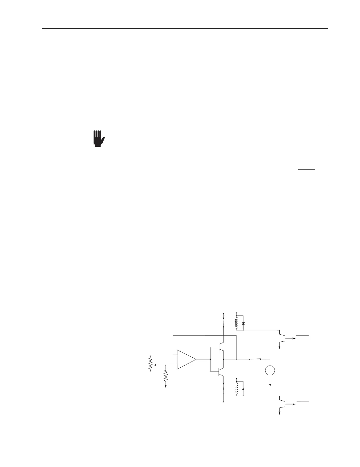
When operating between end limits, the limit switch signals UpLim and
DnLim are high. A low signal indicates the limit has been reached. A sug-
gested motor drive circuit is shown in Figure 8-11 which includes relays
that are used to disable the drive signal when the limit is reached in each
direction. Provide an off switch as shown to ensure there is no creep after
M
1
has been properly positioned. Make all the appropriate connections to
ground. Remember to provide the +5 Vdc and the 220 Ω pull-up resistors
as shown in Figure 8-10 to drive the optical side of the limit switches, and
the 10 kΩ pull-up resistors for the limit switch output signals. The +5 Vdc
in Figure 8-10 is the same +5 Vdc that should be used to drive the relays in
Figure 8-11.
The limit switches restrict the total range of coarse travel to about 1.25 cm.
This corresponds to a change in laser repetition rate of over 500 kHz. Note
that when you tune a fs Tsunami laser over a given optics set, as the disper-
sion is adjusted for optimum pulse width performance, the repetition rate
(cavity length) is changed by over 300 kHz. The coarse control allows you
to maintain a reasonably constant cavity length as the wavelength is tuned.
Figure 8-11: A suggested schematic for driving the coarse position M
1
motor.
You must employ the limit switches if you intend to drive M
1
using your
own equipment. This insures the motor drive mechanism will not be
damaged if you exceed the drive limits. Any such damage is not covered
under your warranty!
Warning!
–
+
M
M
1
Motor
*
LF356
2N3906
100 kΩ
–12 V
10 kΩ
+12 V
2N3904
*
+12 V
+5 V
1N4004
2N3906
2N3906
Off
13
1
+5 V
–12 V
1N4004
UpLim
DnLim
* 5 V N.C. Relay