Tsunami Mode-Locked Ti:sapphire Laser
B-6
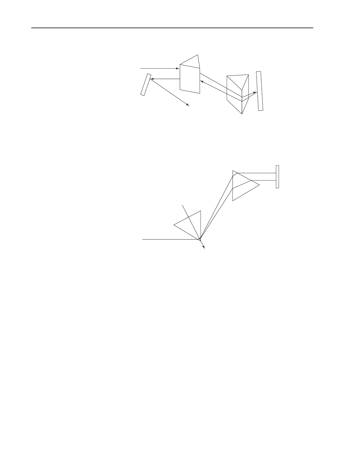
Figure B-4: Using two prisms to compensate for positive GVD.
This setup allows the higher frequencies (blue) to catch up with the lower
frequencies (red). This is not intuitively obvious, since it appears that the
higher frequencies actually travel a longer path length than the lower fre-
quencies. However, it is the second derivative of the path with respect to
wavelength, d
2
P/dλ
2
, that determines the sign of the GVD. In Table B-3 and
Table B-4 dispersion values at 800 nm are provided for materials and grat-
ing prism pairs. The dispersion, D
w
, is expressed in units fs
2
/cm of path
length.
The reason for double passing the prisms is to maintain the spatial profile
of the beam. If only one pass through the prism is used, the output is spa-
tially chirped. While the spacing of the prisms provides negative disper-
sion, the prism material actually adds more positive dispersion to the
system. This can be used to our advantage in the optimization of a prism
pre-compensator.
Prism 1
Higher Frequency
(Blue)
Lower Frequency
(Red)
Direction in which to translate Prism 1
to add more positive GVD.
Prism 2
Prism 1
Prism 2
High
Reflector
Input Beam
Pick-off
Mirror
To
Autocorrelator/
Experiment
Side View: Beam path shown for a particular
frequency component of the pusle.
Top View: Dispersion shown.