Operation 5
Handling the battery
Battery commissioning
CAUTION
Risk of accident, risk of injury from crushing and
shear points
Before each shift, check that the optional battery
lock is in perfect condition and functions correctly.
Always actuate the swing bolts with just one hand
and make sure that fingers are kept away from the
rotation and clamping range.
A proper commissioning must be performed if
you have ordered your truck without a battery
or if you are supplied with a dry pre-charged
battery, as it has had to be transported over
a long distance (e.g. from overseas). Please
follow the information and guidelines from the
battery manufacturer precisely.
If the battery was procured separately to
the truck, the following must be checked by
authorised service personnel:
• Nominal voltage
• Required minimum weight
• Fitted battery male connector
• Battery discharging chara
cteristic curve
1
2
Adjusting the battery l
ock
Adjustment instructi
ons
Battery trays for traction batteries are manu-
factured with relatively large tolerances. To
ensure that the lock of the battery frame in
which the battery sits is in good working or-
der, its bump stops must be adjusted. This
happens in the factory during commissioning.
However, if the customer procures the battery
himself or if the battery is replaced, the adjust-
ment must be carried out on site.
– For instructions of how to install and remove
the battery, as well as for how to handle
the battery, refer to the chapter entitled
"Replacing the battery using a crane".
– Unlock the battery f
rame and slide it out. If
necessary, use an ex
tension cable and an
adjacent battery.
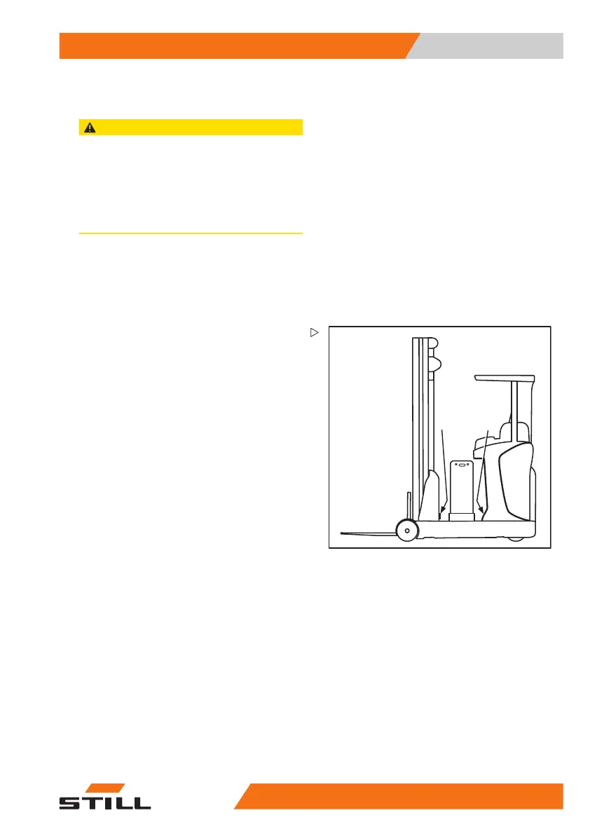
– Screw both rubber buffers fully into the
exterior of the control compartment (1). Do
not use flat washers.
– Insert the battery into the changing frame
and fasten it to the load-side wall.
– Slide in the batte
ry frame.
If the locking mechanism makes contact
with the rubber buffers (1) once the lock is
engaged, no further adjustment is required.
50
988078001 [EN] 211