V/D
S
ERIES
E
LECTRICAL ASSEMBLIES
4-4 Revision: 2.1
567891011 1
4
12 13 14 17 21218
15 16
23
19 20
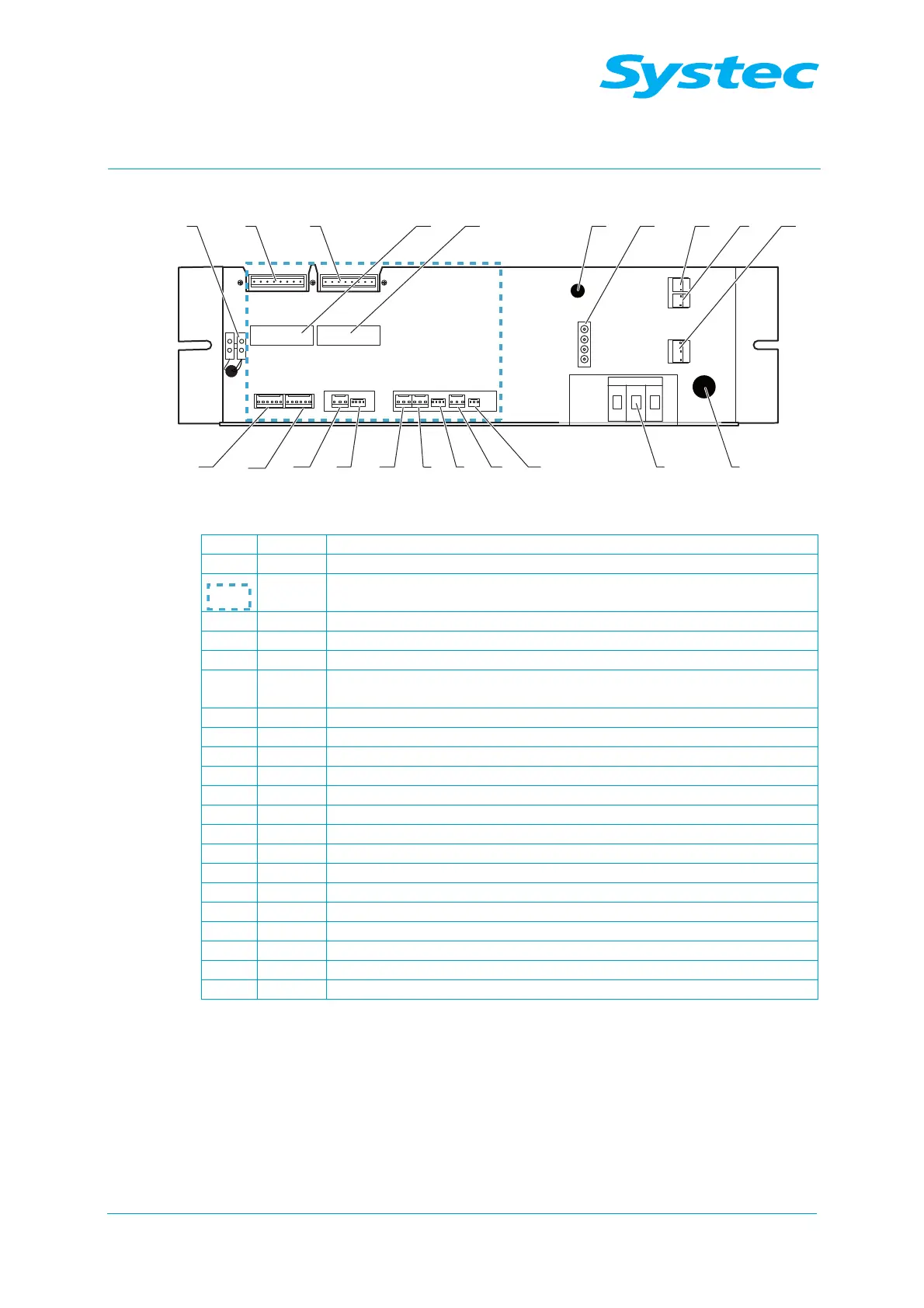
Fig. 2: Underside of the E-Box V-40 – 55, D-45
1 10 A control fuse (F4)
2 Neutral terminal (N)
Connections on analogue circuit board AS1002 (see chapter Fig. 6:
unterhalb)
3 JP14 Electrodes (E1 – E3)
4 JP6 Drain temperature sensor (TS4, drain temp)
5 JP4 Pressure transducer on steam generator (PS1, gen press)
6 JP5 Temperature sensor 2 on sterilisation chamber (TS3, chamber
temp 2)
7 JP3 Flow sensor (TS2, condense temp)
8 JP1 Pressure transducer on sterilisation chamber (PS2, chamber press)
9 JP2 Temperature sensor 1 on sterilisation chamber (TS1, chamber temp)
10 JP11 Digital inputs
11 JP10 Digital inputs
12 12 V DC terminal strip
13 JP9 Digital outputs
14 JP7 Digital outputs
15 JP16 Test points
16 JP17 Test points
17 Radial fan circuit-breaker (F11)
18 AC-1 connector
19 JP7 AC_T1, 230 V output for water feed pump
20 JP4 AC_T1, 230 V output for vacuum pump (M2)
21 JP3 AC_T1, 230 V AC input
 Loading...
