V/D
S
ERIES
M
ECHANICAL ASSEMBLIES
3-20 Revision: 2.1
3.2.6 DX-2D
21 2322
24 2625
27
29
28
61 6362
37 3938
34 3635
31 3332
64 6665
67 6968
71 7372
47 4948
44 4645
41 4342
74 7675
77 7978
51 5352
54 5655
57 5958
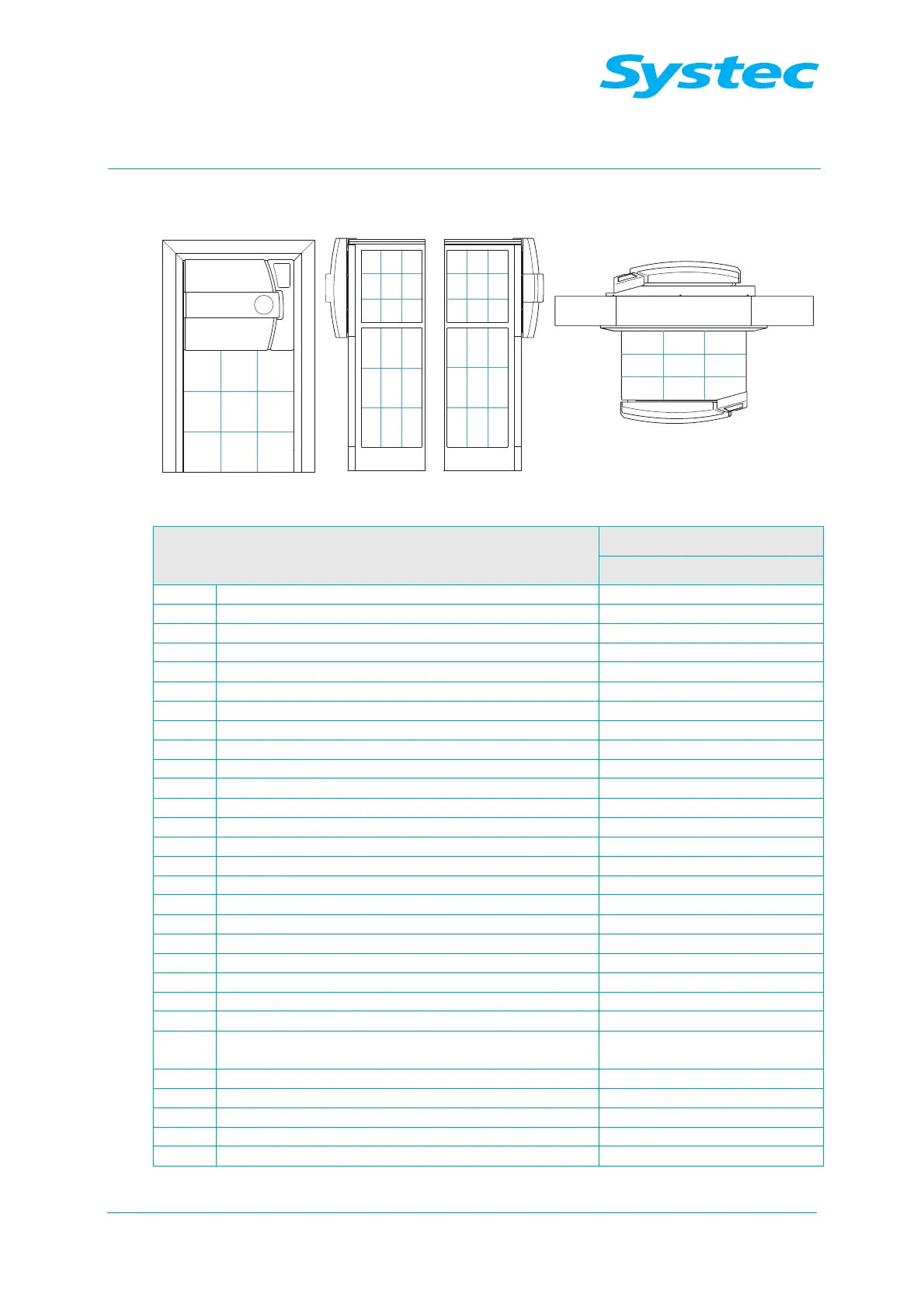
DX-2D: Layout diagram of device side, right, left and top
Component Position in layout diagram
DX
Steam generator 29
Pneumatic assembly 1 21
Pneumatic assembly 2 63
BV1 Manual drain tap for steam generator 28
D1 Steam air extractor for sterilisation chamber 75
D2 Steam air extractor (Super Dry) 75
F1 Demineralised water flow monitor 26
F2 Vacuum flow monitor 78
M1 Demineralised water feed pump 26
M2 Vacuum pump 27
M3 Air compressor 66
N1 Needle valve for air extraction 75
NR6 Needle no-return valve – “Blow out cooling coil” 21
NR7 Needle no-return valve for cavitation protection 27
P1 Manometer for external compressed air 78
P2 Manometer for internal compressed air 66
PR1 Pressure reducer for external compressed air 78
PR2 Pressure reducer for cooling water 78
PS1 Pressure transducer for steam generator 64
PS2 Pressure transducer for sterilisation chamber 49
PV1 Compressed air reservoir 66
PV2 Exhaust filter 57
R1 No-return valve for demineralised water 29
R2
No-return valve on pressure transducer for steam
generator
64
R3 No-return valve for cooling water 78
R4 No-return valve for compressed air inlet 58
R5 No-return valve for drain 72
R6 No-return valve for air compressor 66
R7 No-return valve for vacuum 48