V/D
S
ERIES
M
ECHANICAL ASSEMBLIES
Revision: 2.1 3-33
3.3.2 V-40 – 55, D-45
Principle
The devices are equipped with an automatic door lock. Two locking pins
mesh with the two holes on the device and lock the door securely.
The controller then checks the correct procedure using a series of inputs
and outputs, thus ensuring safe operation of the device.
Closing
Closing the door triggers a chain of events to close and lock the door.
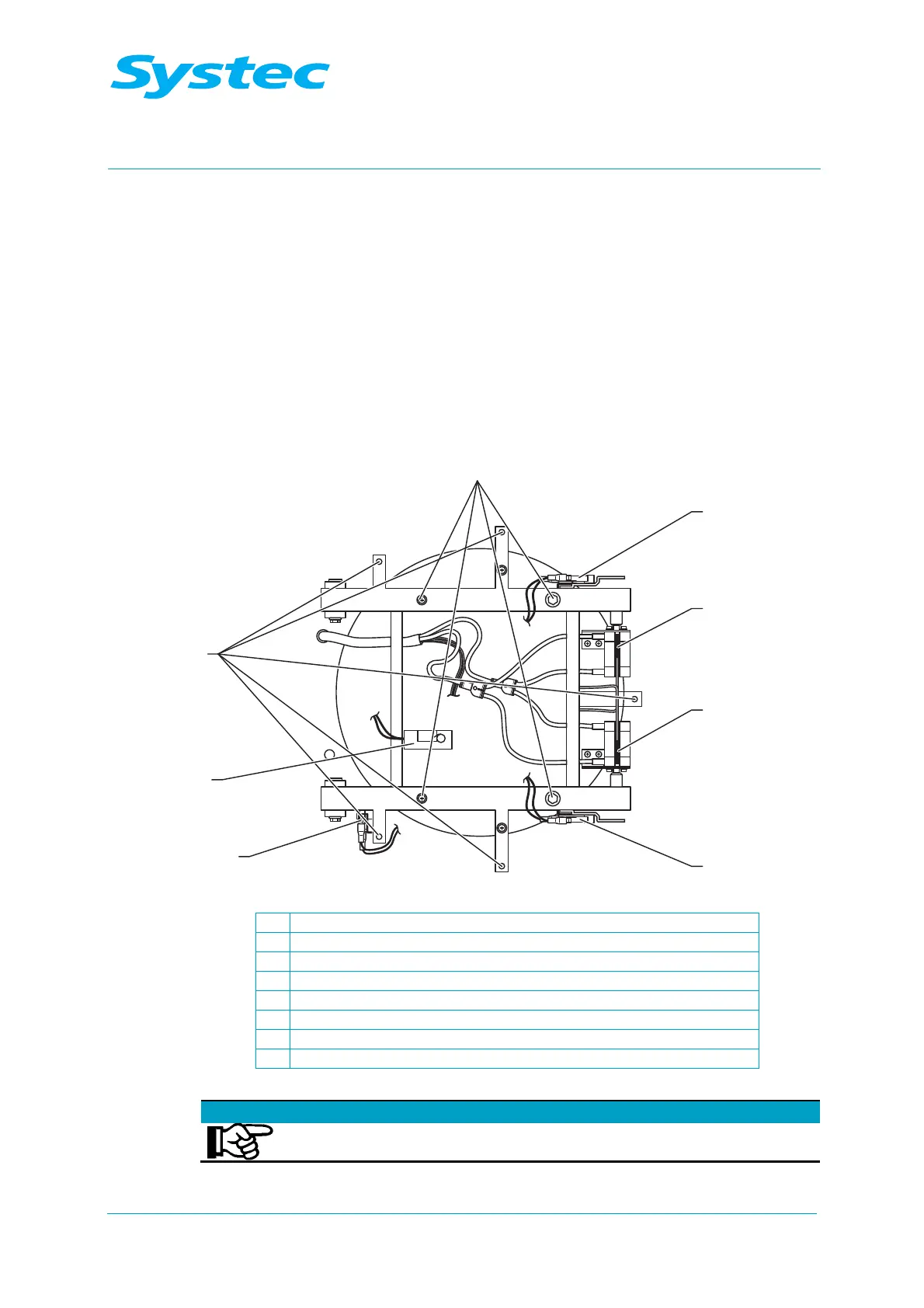
Fig. 13: Position of the door switch and fastening screws (door cladding removed)
1 Door switch (Door Close)
2 Reed contact for digital input (Ring Close 4/Gasket sw)
3 Reed contact for digital input (Ring Close 2/3)
4 Toggle switch for digital input (Ring Open/Ring Close)
5 Tilt switch (D series only)
6 Tilt switch (V series only)
7 Fastening screws for door cladding
8 Fastening screws for container door
Note
The door is suspended so that it also seals in a vacuum.