V/D
S
ERIES
M
ECHANICAL ASSEMBLIES
Revision: 2.1 3-53
3.7 Cooling
3.7.1 Position and function
Water cooling with support air
Operating principle:
After the sterilisation phase has ended, the steam in the sterilisation
chamber is replaced with sterile, filtered, compressed air (support air) and
the cooling coil is flooded with cooling water. After the unloading
temperature is reached, the support air is vented and atmospheric
conditions are established.
The pressure reducer on the input for support air is factory set to 6 – 7 bar
and can be read from the manometer on the pressure reducer.
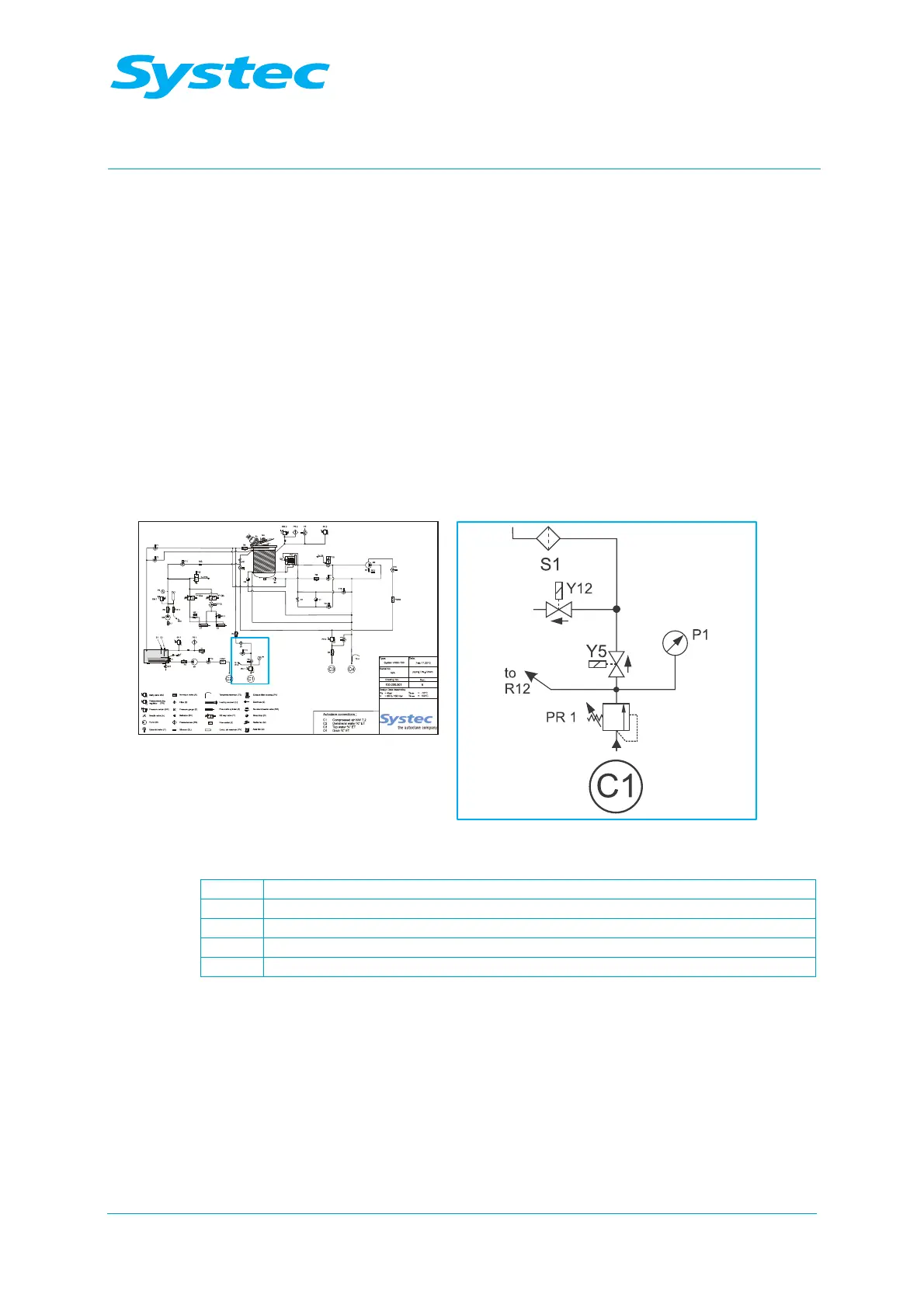
Fig. 30: Components on the “Cooling” assembly
P1 Manometer
PR1 Pressure reducer for support air
Y5 Support air valve
Y12 Vacuum breaker
S1 Sterile air filter
Water cooling:
The temperature of the unprocessed, cooling water in the cooling coil is
checked using parameter 40 (SaveWaterTemp). If the temperature
measured is greater than 40 °C, the cooling coil is supplied at the
maximum flow rate. If a lower temperature is measured, this is a sign that
the cooling water is no longer removing much energy. Pulsing the water
flow will then reduce the water usage, thus saving energy.