V/D
S
ERIES
E
LECTRICAL ASSEMBLIES
4-20 Revision: 2.1
4.2.2 Analogue circuit board
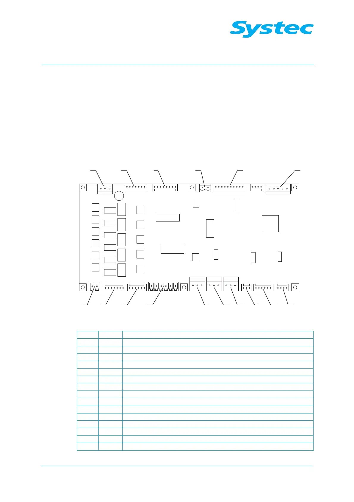
The analogue circuit board on the D-23 connects all analogue and digital
inputs and outputs with the digital circuit board of the D-23. The
connection is made from the JP6 connection on the analogue circuit board
to the JP8 connection on the digital circuit board.
The analogue circuit board on the D-23 is equipped with its own
microprocessor, which stores the gain and offset values from the
calibration process.
1 2 3 4 5 6
78910111216 1315 14
Fig. 20: Analogue circuit board on the D-23
1 JP7 Power supply for the analogue circuit board (5 V/13 V)
2 JP15 Power supply digital outputs
3 JP12 Digital inputs
4 JP11 Digital output for motor control (door)
5 JP10 Printer
6 JP6 Power supply and communication to digital circuit board
7 JP1 Drain temperature sensor (TS4, drain temp)
8 JP17 Pressure transducer on sterilisation chamber (PS2, chamber press)
9 JP2 Pressure transducer on steam generator (PS1, gen press)
10 JP3 Temperature sensor 1 on sterilisation chamber (TS1, chamber temp)
11 JP5 Flow sensor (TS2, condense temp)
12 JP18 Temperature sensor 2 on sterilisation chamber (TS3, chamber temp 2)
13 JP4 Analogue inputs E1 – E3, Res. High elect. (B6), E6, TS4.2
14 JP16 Digital outputs
15 JP13 Digital outputs
16 JP14 24 V AC for digital outputs