V/D
S
ERIES
E
LECTRICAL ASSEMBLIES
Revision: 2.1 4-13
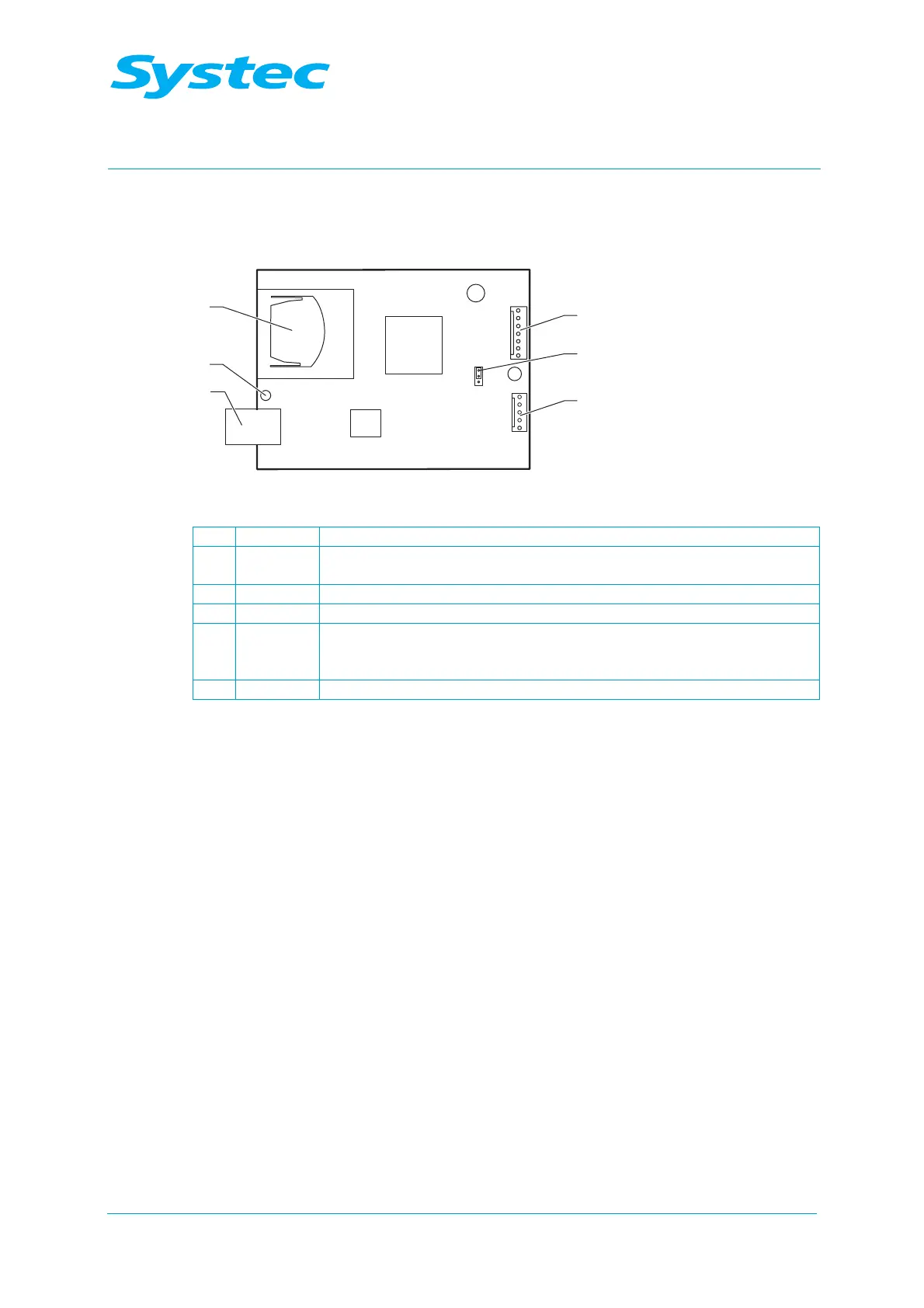
4.1.8 SD card circuit board
This circuit board is used for saving data on an SD card.
Fig. 12: SD card circuit board
1 JP3 Serial interface connection from digital circuit board DS1002
2 JP2
Selector for interface protocol RS-232 or RS-485 (RS-232 2–3 short,
RS-458 1–2 short)
3 JP1 Serial interface output
4 USB port for service
5 LED – Red: Error
– Yellow: Writing
– Green: Ready – SD card can be inserted or removed
6 SD card Slot for SD card
SD card specification:
− Standard, max. 2 GB (SD 1.1)
− Formatted in FAT file system
 Loading...
