V/D
S
ERIES
M
ECHANICAL ASSEMBLIES
3-26 Revision: 2.1
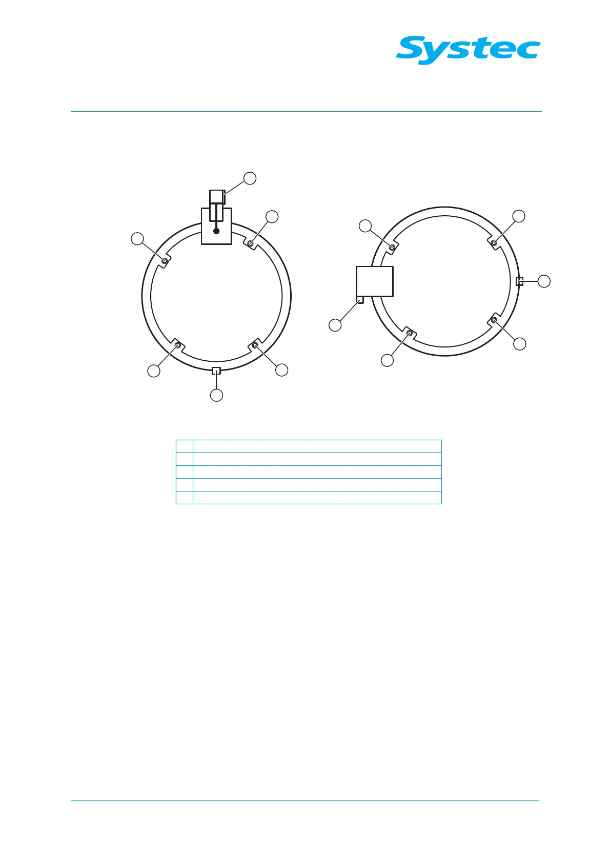
Ring switches
Fig. 8: Position of the microswitches that monitor the door lock
1
Ring Close 3 (both switches in series)
2
Ring Close 2
3
Gasket Switch
4
Ring Close 4
5
Door Close
The locked door is monitored using microswitches (Ring Close 2 to Ring
Close 4) as well as the reed contact on the locking cylinder for the locking
shoe (Z2, Ring Close, see Fig. 9: unterhalb). When the door is open, the
position of the opened locking ring is only displayed via the reed contact
on the locking cylinder of the scissor mechanism (Z1, Ring Open, see
Fig. 9: unterhalb).