V/D
S
ERIES
E
LECTRICAL ASSEMBLIES
Revision: 2.1 4-3
Observe the electrical safety regulations when performing
maintenance work on the electrical system!
Remove the power to the equipment
Earth and short-circuit
Cover or isolate adjacent or live components
Isolate the equipment
Secure the equipment against accidental restart
4.1 Overview – Electrical assemblies V/D-40 – 200
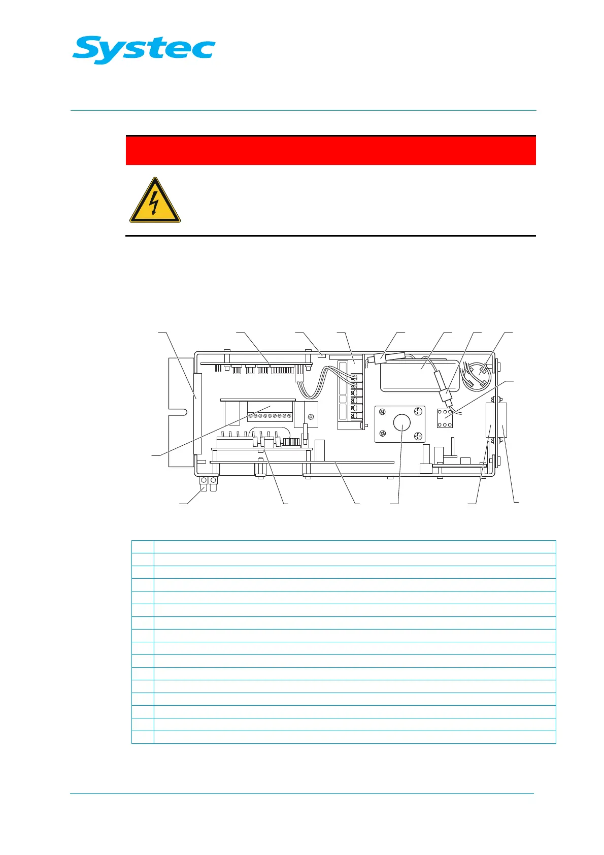
4.1.1 Electronics box on V-40 – 55/D-45 devices
− The electronics box (E-Box) contains most of the electrical assemblies.
It is located on the rear of the device behind the service door.
15
16
1112
21 3 4 765 8
9
101314
Fig. 1: Front of the E-Box V/D-40 – 55
1 Fan
2 Digital circuit board DS1002 (see chapter 4.1.5 unterhalb)
3 5 V fixed voltage controller, LM1085 (see chapter 4.1.9 unterhalb)
4 Power supply RD35A (see chapter 4.1.12 unterhalb)
5 800 mA primary fuse for toroidal transformer (F5, 4 x 20 mm)
6 Toroidal transformer (see chapter 4.1.11 unterhalb)
7 5 A secondary fuse for toroidal transformer (F6, 4 x 20 mm)
8 Anti-interference capacitor (main filter)
9 Neutral terminal (N)
10 Solid state relay for top exhaust valve (Y16)
11 Solid state relay for air compressor
12 Solid state relay for heater (5 V DC)
13 Analogue circuit board AS1002 (see chapter 4.1.3 unterhalb)
14 Extension board (see chapter 4.1.4 unterhalb)
15 12 V DC terminal strip
16 Motor control board for radial fan (see chapter 4.1.6 unterhalb)