V/D
S
ERIES
E
LECTRICAL ASSEMBLIES
Revision: 2.1 4-5
4.1.2 Electronics box on V/D 65 – 200 devices
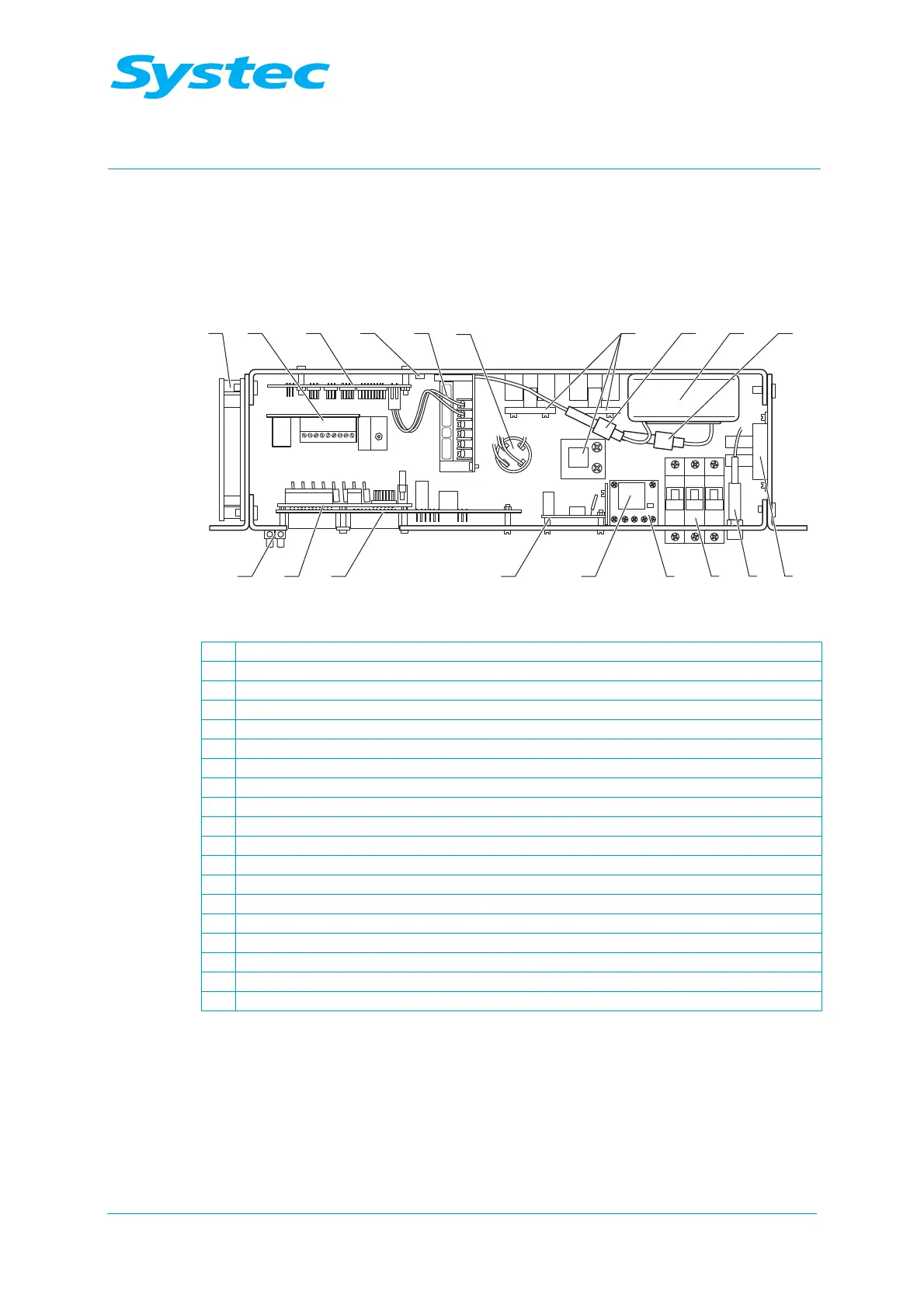
− The E-Box contains most of the electrical assemblies. It is located on
the rear of the device behind the service door.
16 15171819
1 2 3 4 5
5 6
9
1087
14
13 12 11
Fig. 3: Front of the E-Box (V/D 65 l – 200 l)
1 Fan
2 Motor control board for radial fan (see chapter 4.1.6 unterhalb)
3 Digital circuit board DS1002 (see chapter 4.1.5 unterhalb)
4 5 V fixed voltage controller, LM1085 (see chapter 4.1.9 unterhalb)
5 Power supply RD35A (see chapter 4.1.12 unterhalb)
6 Anti-interference capacitor (main filter)
7 Solid state relay for heater (SSR 1 – 3)
8 5 A secondary fuse for toroidal transformer (F6, 4 x 20 mm)
9 Toroidal transformer (see chapter 4.1.11 unterhalb)
10 800 mA primary fuse for toroidal transformer (F5, 4 x 20 mm)
11 Solid state relay for top exhaust valve (Y16)
12 10 A control fuse (F4)
13 Circuit breaker (F1 – F3)
14 Heater contactor (K1) (see chapter 4.1.14 unterhalb)
15 Noise filter for K1
16 AC-T1 board (see chapter 4.1.7 unterhalb)
17 Analogue circuit board AS1002 (see chapter 4.1.3 unterhalb)
18 Extension board (see chapter 4.1.4 unterhalb)
19 Terminal strip