V/D
S
ERIES
E
LECTRICAL ASSEMBLIES
4-6 Revision: 2.1
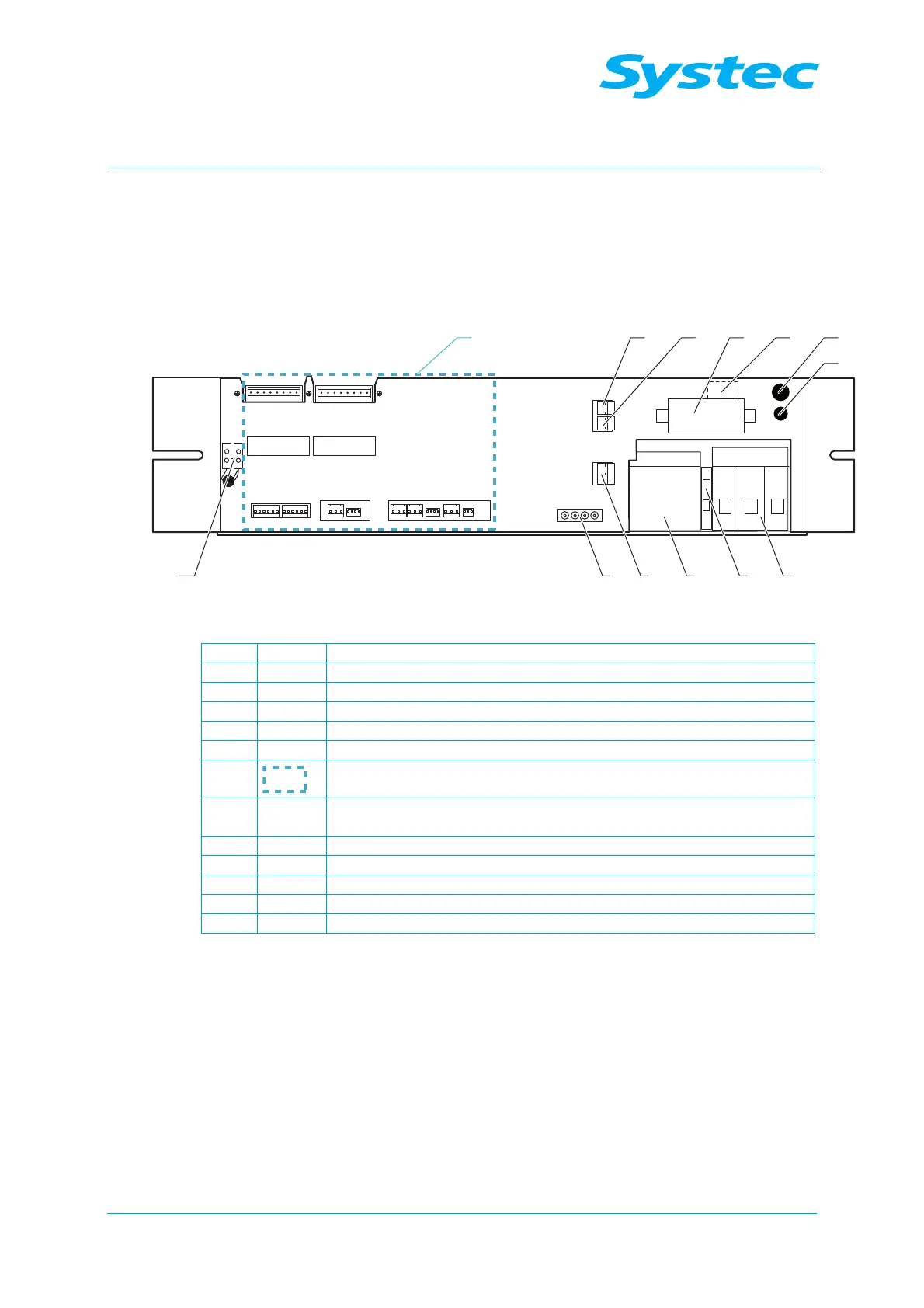
Fig. 4: Underside of the E-Box (V/D 65 l – 200 l)
1 Circuit breaker (F1 – F3)
2 Neutral terminal (N)
3 Heater contactor (K1)
4 JP3 AC_T1, 230 V AC input
5 AC-1 connector
6 12 V DC terminal strip
7
Connections on analogue circuit board AS1002 (see Fig. 6:
unterhalb)
8 JP7
AC_T1, 230 V output for water feed pump /
AC_T1, 230 V output for air compressor
9 JP4 Vacuum pump (M2)
10 Solid state relay for circulation pump
11 Switching transistor for air compressor output
12 10 A control fuse (F4)
13 Radial fan circuit-breaker (F11)