V/D
S
ERIES
M
ECHANICAL ASSEMBLIES
Revision: 2.1 3-27
Scissor mechanism
The locking ring is opened and closed by the scissor mechanism and,
when closed, is securely kept in place by a locking shoe.
The scissor mechanism (and thus the locking ring and locking shoe
safeguard) is closed by two opposing pneumatic cylinders (see Fig. 9:
unterhalb).
The pneumatic system of the scissor mechanism is fitted to a plate so that
the entire assembly can be fitted and removed as a single component (see
“Replacing the scissor mechanism”).
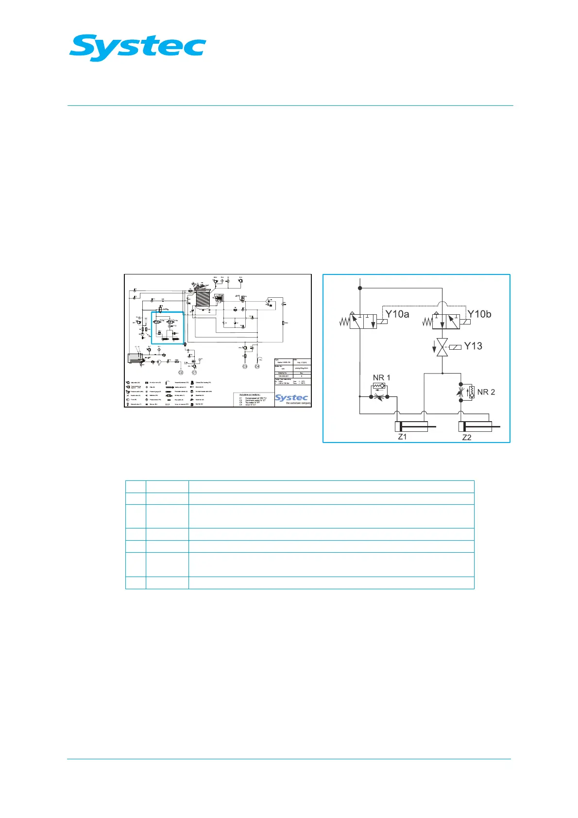
Fig. 9: Controlling the scissor mechanism: Position on pipe connection diagram
1 Y10a Solenoid valve on locking ring
2 Y13 Solenoid valve on locking ring (230 V)
3 NR2
Throttle no-return valve for delayed extension of the cylinder for
the locking shoe (Z2)
4 Z2 Locking shoe on cylinder (Ring Close)
5 Z1 Locking ring on cylinder (Ring Open)
6 NR1
Throttle no-return valve for delayed retraction of the cylinder for
the locking ring (Z1)
7 Y10b Solenoid valve on locking ring