V/D
S
ERIES
M
ECHANICAL ASSEMBLIES
3-36 Revision: 2.1
Position and function
Type:
Serial No.:
Date:
Rev.:
Systec VX 40-55
N/A
Feb.18.2010
Drawing No.:
piping DN 10mm
Design Data Assembley
Ps = 3bar
V = 45,5 bis 59,5 l
Ts = -10°C
Ts = 150°C
min
max
Safty valve (SV)
Pressurereducing
regulator (PR)
Pressure switch (SW)
Needle valve (N)
Pump (M)
Solenoid valve (Y)
No-return valve (R)
Filter (S)
Pressure gauge (P)
Ballvalve (BV)
Pressursensor (PS)
Silencer (SL1) Compressed air res. (PV)
3/2 way valve (Y)
Pneumatic cylinder (Z)
Heating element (H)
Temperaturesensor(TS)
Flow switch (F)
Radial fan (M)
Steamtrap (D)
No-return/needle valve (NR)
Electrode (E)
Exhaust filter housing (PV2)
C1 Compressed air NW 7,2
C2 Demineral water ¾” ET
C3 Tap water ¾” ET
C4 Drain ¾” ET
Autoclave connections
:
100.000.002
10
Cut off thermostat (CUT)
PV1
SL1
CUT
E2E1
R1
PS 1
SV 1
BV1
R2
Y14
M1
FSW1
C2
TS1
C4
Y10a Y10b
Y13
Z2
Z1
PR1
to
R12
to
R12
PR 1
P1
Y5
C1
Y2
D2
SW 1
R6
M3
P2
SV 2SW 2 PS 2
Y6
PR 2
Y1
R4
Y15
FSW2
M2
R7
Y8
R13
N7
Y12
S1
Y4
R3
TS 4
C3
Y9
Y7
S2
R5
N1
D1
TS 2
M4
PV1
H1
Y10a Y10b
Y13
Z2
Z1
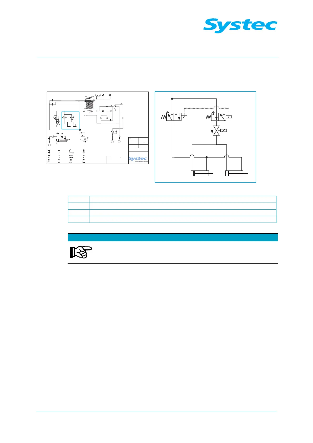
Fig. 15: Door lock: Position on pipe connection diagram
Y10a Solenoid valve on locking cylinder
Y10b Solenoid valve on locking cylinder
Y13 Solenoid valve on locking cylinder (230 V)
Z1, Z2 Locking cylinder with locking bolts
Note
The solenoid valve Y13 ensures that the locking bolts remain
retracted when the door is opened and the device is switched
off.