V/D
S
ERIES
E
LECTRICAL ASSEMBLIES
Revision: 2.1 4-9
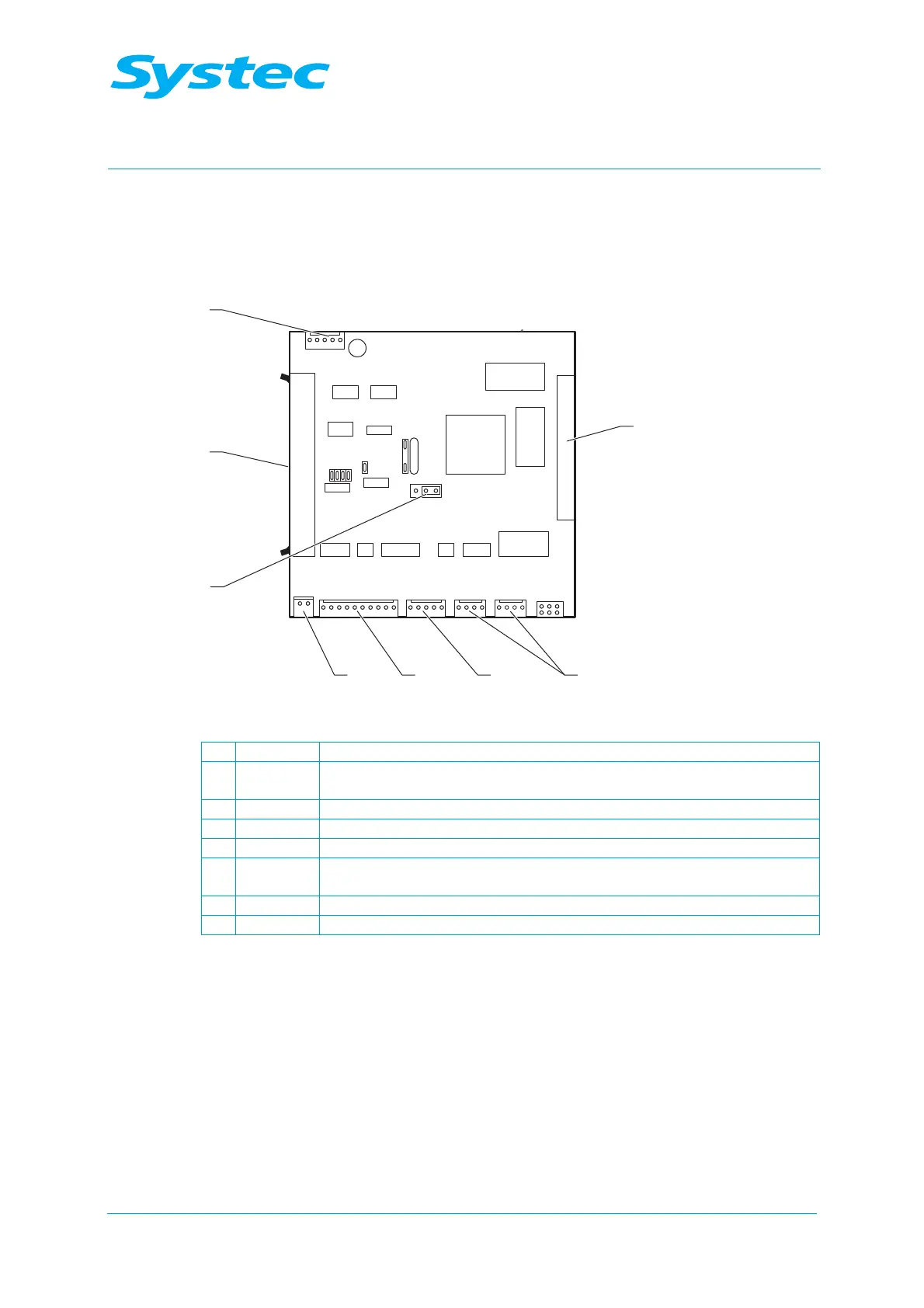
4.1.5 Digital circuit board DS1002
The main controller (processor) is located on the digital circuit board. The
device software is stored here.
2
1
345
6
7
8
JP5
JP12
1
JP6
JP7
JP8
JP13
JP11
JP1
JP9
Fig. 8: Digital circuit board DS1002
1 JP9 Test points
2 JP8/JP13 Connection for control unit (can be plugged into JP8 or JP13 – the
function is identical)
3 JP7 Interface connector (RS-232 / RS-485)
4 JP6 Connection for printer
5 JP11 Power supply (5 V DC)
6 JP5 Selector for interface protocol RS-232 or RS-485 (RS-232 2–3
connected, RS-485 1–2 connected)
7 JP1 Connection for 40-pin ribbon cable to analogue circuit board AS1002
8 JP12 Digital outputs (5 V DC)