V/D
S
ERIES
M
ECHANICAL ASSEMBLIES
3-28 Revision: 2.1
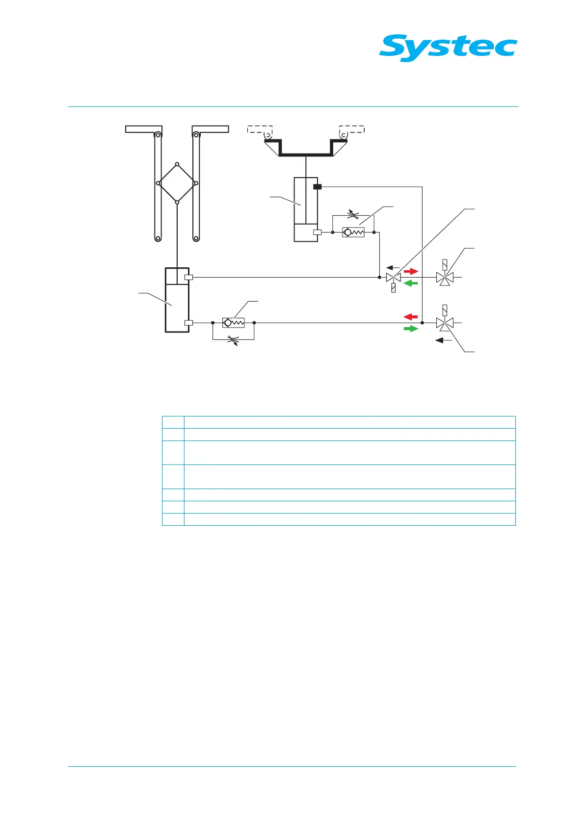
Fig. 10: Function diagram of the scissor mechanism, locking ring open
red = open, green = close
1 Locking ring on cylinder (Z1)
2 Locking shoe on cylinder (Z2)
3
Throttle no-return valve for delayed extension of the cylinder for the
locking shoe (Z2)
4
Throttle no-return valve for delayed retraction of the cylinder for the locking
ring (Z1)
5 3/2-way valve, normally open
6 3/2-way valve, normally closed
7 Solenoid valve on locking ring (Y13, 230 V)
Function description:
The locking cylinder Z1 opens (upper position) or closes the locking ring of
the sterilisation chamber. When the locking ring is closed, the locking
cylinder Z2 moves over the connection of the scissor mechanism and the
locking ring and thus fixes the locked ring. Both locking cylinders are
closed or opened via the opposing connections of the pneumatic assembly
(see chapter 3.10.2 unterhalb). Throttle no-return valves in front of each
lower connection of the locking cylinders ensure that the locking shoe
moves to the locking position with a delay after the locking ring closes.
The no-return valves also ensure that the scissor mechanism is only
opened when the locking shoe has released the screw connection
between the scissor mechanism and locking ring. The solenoid valve on
the locking ring (Y13) ensures that the locking ring remains open when the
device is switched off with the door open.