V/D
S
ERIES
E
LECTRICAL ASSEMBLIES
4-26 Revision: 2.1
Installing the printer
• Remove the service doors or door cladding, when necessary.
• Open the cover of the printer.
• Insert the printer into the housing.
• Position the threaded bolt horizontally from behind.
• Tighten the 4 screws.
• Insert the printer paper.
• Close the cover.
• Connect the printer to the E-Box.
• Reattach the service door.
• Switch on the device and check the printout.
Connecting the printer to the E-Box
• Connect the earth cable with eyelet to the housing.
• Connect the power supply cable.
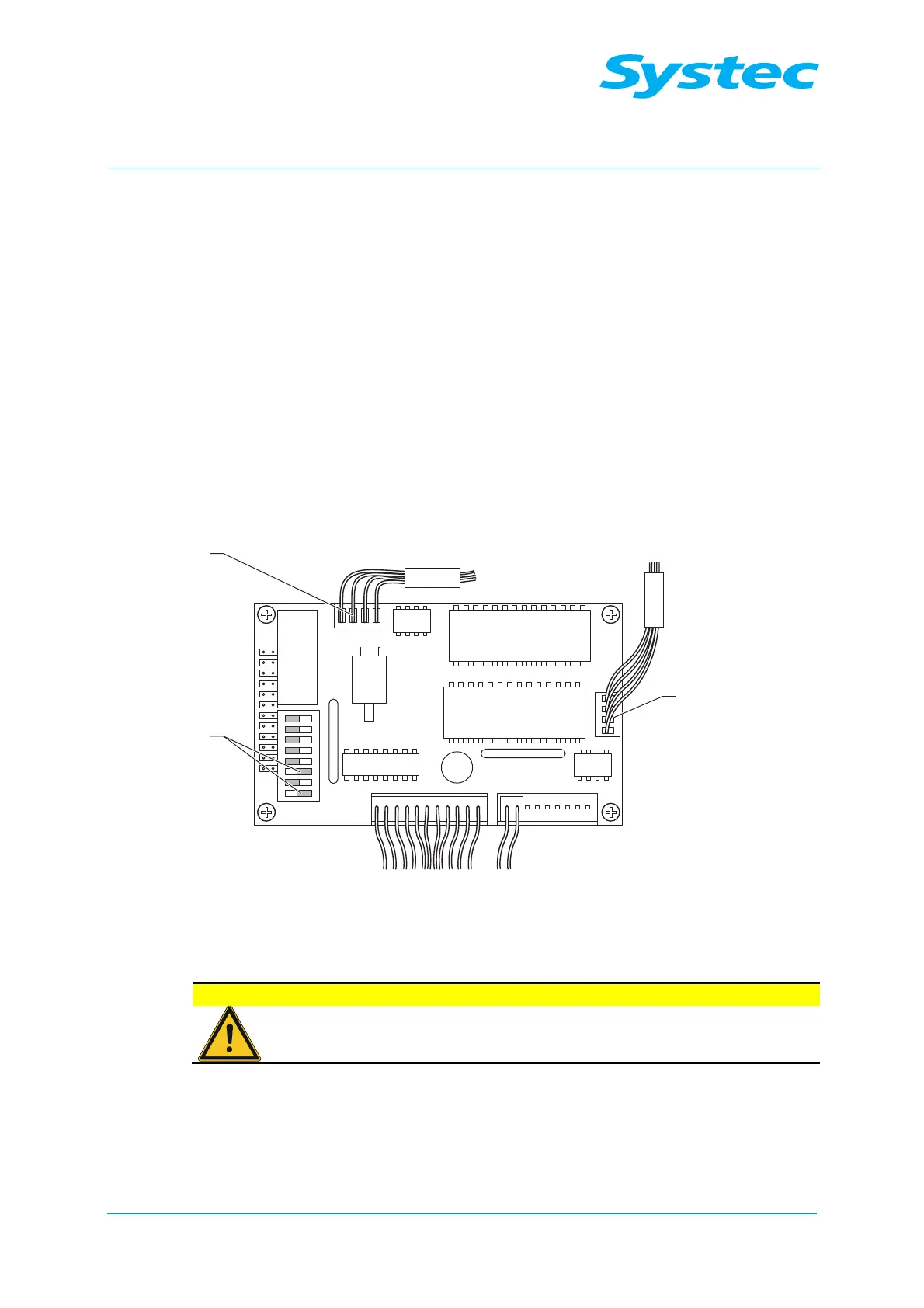
Fig. 27: Connecting the printer to the E-Box
• Plug the connector into the digital circuit board.
Do not confuse CN2 and CN5!
Make sure that CN2 (3) and CN5 (1) are not confused, as
wrong connections will damage the printer.
DIP switches 1 and 3 (2) must be set to “Off”, all others must be set to
“On”.