V/D
S
ERIES
M
ECHANICAL ASSEMBLIES
Revision: 2.1 3-11
21 2322
24 2625
27 2928
11 1312
14 1615
17 1918
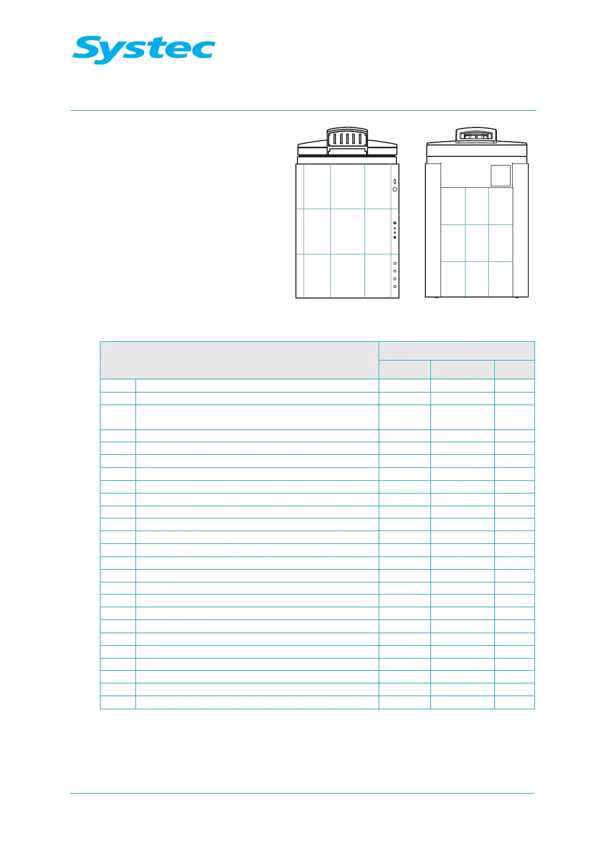
Fig. 1: V-40, V-55: Layout diagram of rear and front
Component
Position in layout diagram
VX VE VB
R5 No-return valve for drain 28 28 28
R6 No-return valve for air compressor 29 17 17
R8 No-return valve for steam inlet (exhaust filter
option)
11
R12 No-return valve for external compressed air 19 19
R13 No-return valve for cavitation protection 15 15
S1 Sterile air filter 14 14 18
S2 Dirt trap sieve 29 29 29
SL1 Silencer for air compressor 15 15 19
SV1 Safety valve on steam generator 17
SV2 Safety valve for sterilisation chamber 21 21 21
Sw1 Pressure switch (7 bar) 29 17 17
Y1 Steam inlet valve 18
Y2 Super Dry valve 18
Y3 Cooling water valve 14 14
Y4 Drain cooling 18 18
Y5 Compressed air inlet valve 14 14
Y6 Atmosphere valve 21 21 21
Y7 Drain valve 29 29 29
Y9 Air extractor valve 27 27 27
Y8 Vacuum valve 29 26
Y11 Blow-out valve for cooling coil 13 13
Y12 Vacuum breaker valve 14 14 18
Y14 Demineralised water inlet valve 19 18
Y15 Pump water valve for vacuum pump 15 15
Y16 Top exhaust valve 28 28 28
Tab. 1: V-40, V-55: Position in layout diagram